Remove a rear riser assembly
Use this information to remove a rear riser assembly.
About this task

The server supports different types of riser cages (see Rear PCIe adapter and riser assembly replacement).
Read Installation Guidelines and Safety inspection checklist to ensure that you work safely.
Power off the server and peripheral devices and disconnect the power cords and all external cables. See Power off the server.
Prevent exposure to static electricity, which might lead to system halt and loss of data, by keeping static-sensitive components in their static-protective packages until installation, and handling these devices with an electrostatic-discharge wrist strap or other grounding system.
Before you remove any component of a RAID array (drive, RAID card, etc.), back up all RAID configuration information.
Procedure
- Remove the riser assembly.
Riser 1 assembly (same for riser 2 assembly)
NoteThe following uses the 3-slot riser cage as an example for illustration. The replacement procedure for the 1-slot riser cage is similar.Figure 1. Riser 1 assembly removal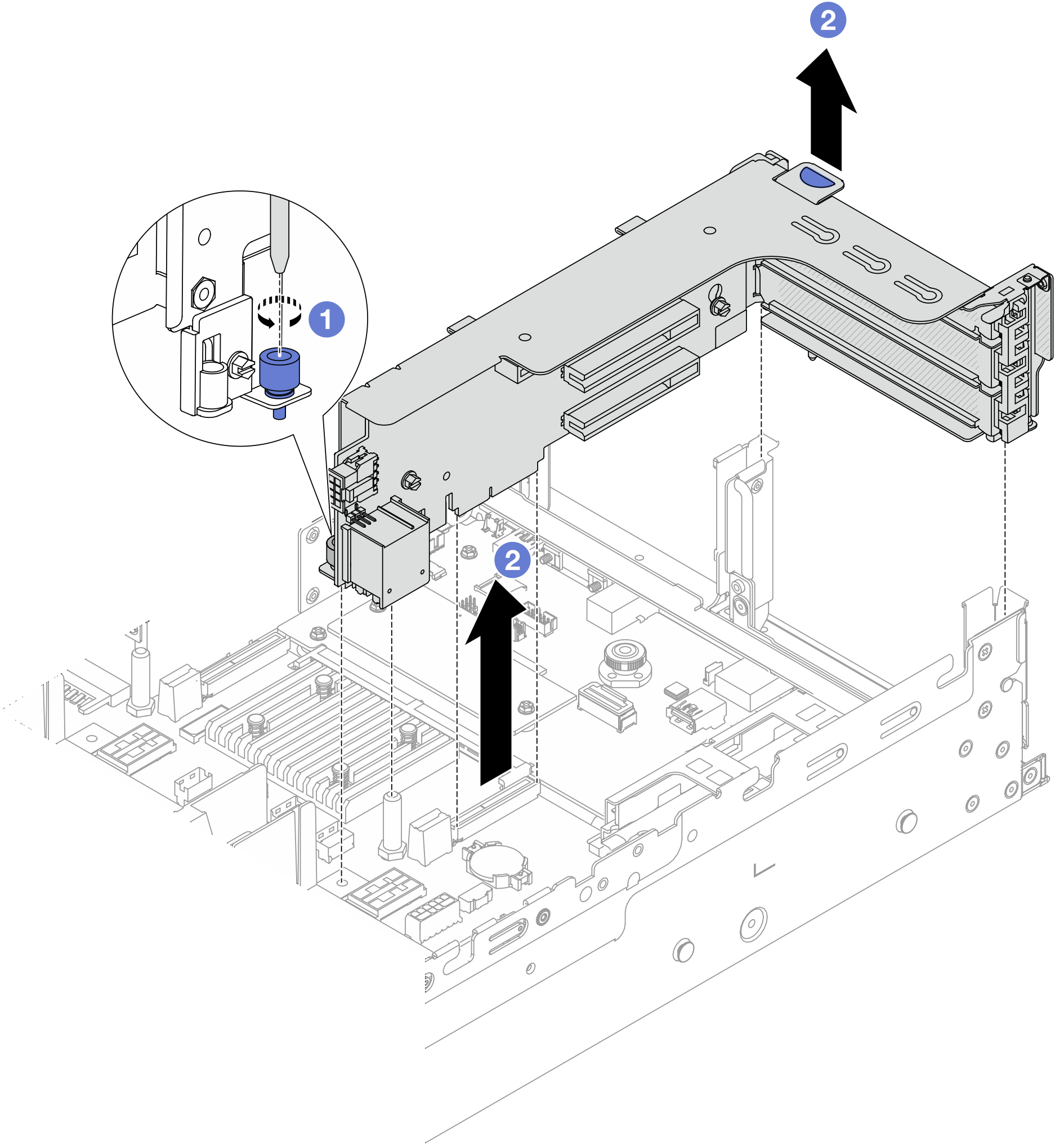
 Loosen the screw that secures the riser assembly.
 Grasp the riser assembly by its edges and carefully lift it straight up and off the chassis.
Riser 3 assembly
NoteThe following uses the Gen 5 riser 3 cage as an example for illustration. The replacement procedure is the same for Gen 4 riser 3 cage.Figure 2. Riser 3 assembly removal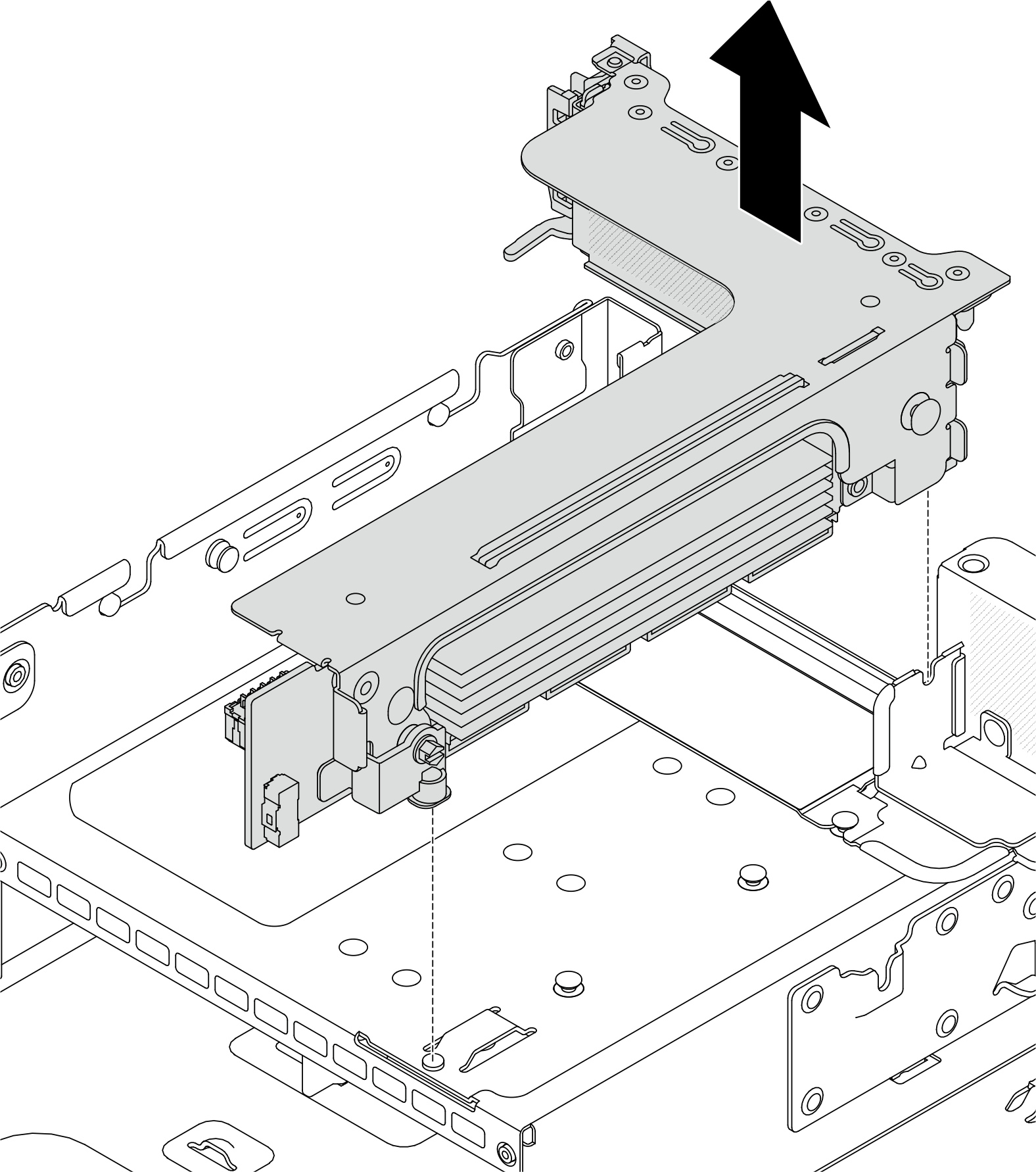
4LP riser 3/4 assembly
Remove riser 3 assembly and riser 4 assembly.
Figure 3. Riser 3/4 assembly removal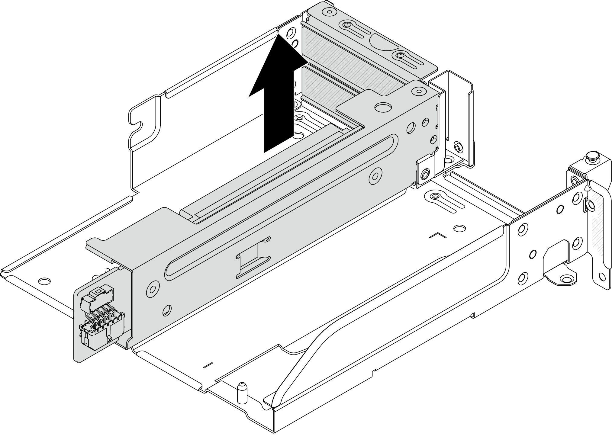
Remove the riser cage tray.
Figure 4. Riser cage tray removal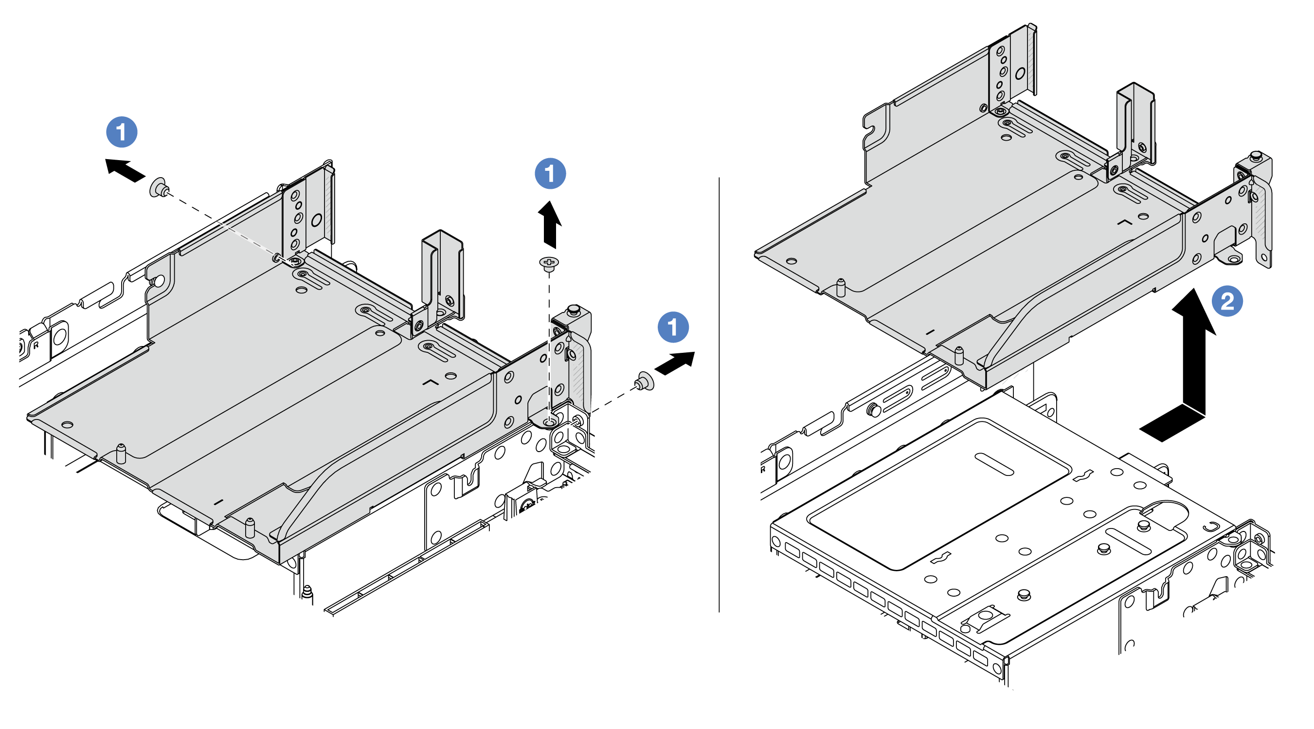
- Remove the screws that secure the riser cage tray.
- Slide the riser cage tray backwards and then lift it out the chassis.
After you finish
Remove the PCIe adapter from the riser assembly. See Remove a rear PCIe adapter.
If you are instructed to return the component or optional device, follow all packaging instructions, and use any packaging materials for shipping that are supplied to you.
Demo video