Install the 2.5-inch-drive backplane
Use this information to install the 2.5-inch-drive backplane. This topic applies only to server models that support 2.5-inch-drive backplanes.


One backplane
Always install either the SATA/SAS 8-bay backplane or the AnyBay 8-bay backplane to drive bays 0–7.
Two backplanes
Two SATA/SAS 8-bay backplanes, two AnyBay 8-bay backplanes, or two NVMe 8-bay backplanes: install the two backplanes to drive bays 0–7 and drive bays 8–15
One SATA/SAS 8-bay backplane and one AnyBay 8-bay backplane: install the AnyBay 8-bay backplane to drive bays 0–7; install the SATA/SAS 8-bay backplane to drive bays 8–15
Three backplanes
Three SATA/SAS 8-bay backplanes, three AnyBay 8-bay backplanes, or three NVMe 8-bay backplanes: install the three backplanes to drive bays 0–7, drive bays 8–15, and drive bays 16–23
Two SATA/SAS 8-bay backplanes and one AnyBay 8-bay backplane: install the AnyBay 8-bay backplane to drive bays 0–7; install the two SATA/SAS 8-bay backplanes to drive bays 8–15 and drive bays 16–23
Two AnyBay 8-bay backplanes and one SATA/SAS 8-bay backplane: install the two AnyBay 8-bay backplanes to drive bays 0–7 and drive bays 8–15; install the SATA/SAS 8-bay backplanes to drive bays 16–23
Two NVMe 8-bay backplanes and one SATA/SAS 8-bay backplane: install the two NVMe 8-bay backplanes to drive bays 0–7 and drive bays 8–15; install the SATA/SAS 8-bay backplanes to drive bays 16–23
Before installing the 2.5-inch-drive backplane, touch the static-protective package that contains the new backplane to any unpainted surface on the outside of the server. Then, take the new backplane out of the package and place it on a static-protective surface.
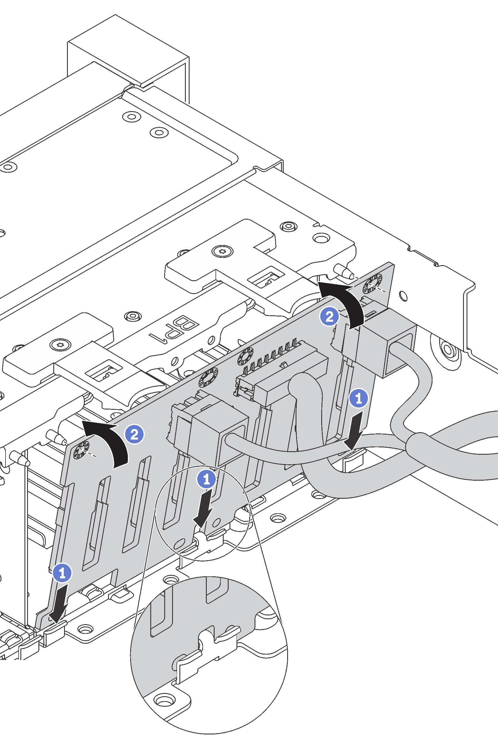
- Insert the bottom of the backplane into the slots on the bottom of the chassis. Then, rotate the backplane to vertical position and align the holes in the backplane with the pins on the chassis and press the backplane into position. The release tabs will secure the backplane in place.Figure 1. 2.5-inch-drive backplane installation
- Apply drive bay labels based on the type of the installed backplanes. Several drive bay labels come with each type of the supported drive backplane:
4–7
Apply this label to drive bays 4–7 if a SATA/SAS 8-bay backplane is installed to drive bays 0–7.
12–15
Apply this label to drive bays 12–15 if a SATA/SAS 8-bay backplane is installed to drive bays 8–15.
4–7 (NVMe)
Apply this label to drive bays 4–7 if an AnyBay 8-bay backplane is installed to drive bays 0–7.
12–15 (NVMe)
Apply this label to drive bays 12–15 if an AnyBay 8-bay backplane is installed to drive bays 8–15.
0-15 (NVMe)
Apply this label to drive bays 0–15 if two NVMe 8-bay backplanes are installed to drive bays 0–15.
16-19 (NVMe)
Apply this label to drive bays 16–19 if a NVMe 8-bay backplane is installed to drive bays 16–19.
16-23 (NVMe)
Apply this label to drive bays 16–23 if a NVMe 8-bay backplane is installed to drive bays 16–23.
The following illustration shows the location for applying the drive bay labels to the server models with AnyBay 8-bay backplanes installed. The location is the same for applying the drive bay labels to server models with SATA/SAS 8-bay backplanes installed. Ensure that the drive bay labels are stuck in the correct location. The labels help you to locate the correct drive during problem determination.Figure 2. Drive bay labels for server models with AnyBay 8-bay backplanes installed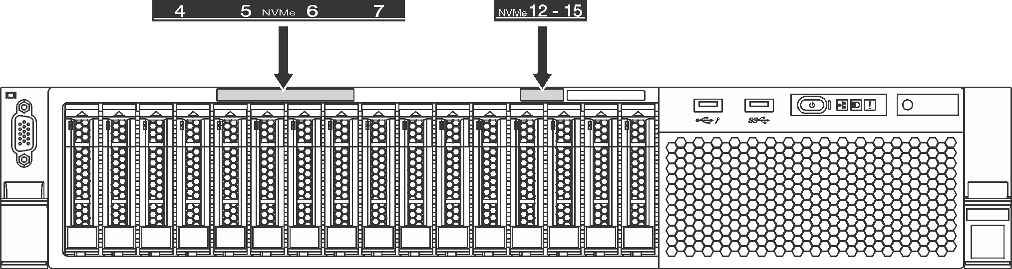
After installing the 2.5-inch-drive backplane, connect the cables to the system board. For information about the cable routing, see Internal cable routing.