Install the front 2.5-inch drive backplane
Follow instructions in this section to install the front 2.5-inch drive backplane.
About this task
2.5-inch SAS/SATA 8-bay backplane
2.5-inch AnyBay 8-bay backplane
2.5-inch NVMe 8-bay backplane
The following table lists the supported backplane combinations. Install the backplane according to your server configuration.
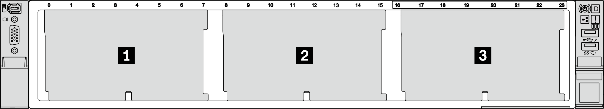
| Backplane quantity | Backplane 1 | Backplane 2 | Backplane 3 |
| 1 |
| ||
| 2 | 8-bay SAS/SATA |
| |
8-bay NVMe | 8-bay NVMe | ||
8-bay AnyBay | 8-bay AnyBay | ||
8-bay AnyBay | 8-bay NVMe | ||
| 3 | 8-bay SAS/SATA | 8-bay SAS/SATA |
|
8-bay SAS/SATA | 8-bay NVMe | 8-bay NVMe | |
8-bay NVMe | 8-bay NVMe | 8-bay NVMe | |
8-bay AnyBay | 8-bay AnyBay | 8-bay AnyBay | |
| 1 | 24-bay expander backplane | ||
Read Installation Guidelines and Safety inspection checklist to ensure that you work safely.
To avoid damage to the drive connectors, make sure that the server top cover is in place and fully closed whenever you install or remove a drive.
To make sure that there is adequate system cooling, do not operate the server for more than two minutes without either a drive or a drive bay filler installed in each bay.
Before you make changes to drives, drive controllers (including controllers that are integrated on the system board assembly), drive backplanes, or drive cables, back up all important data that is stored on drives.
Go to Drivers and Software download website for ThinkSystem SR665 V3 to see the latest firmware and driver updates for your server.
Go to Update the firmware for more information on firmware updating tools.
Procedure
- Install the 2.5-inch drive front backplane.NoteDepending on the specific type, your backplane might look different from the illustration.Figure 2. Installing the 8-bay drive backplane
 Figure 3. Installing the 24-bay expander backplane
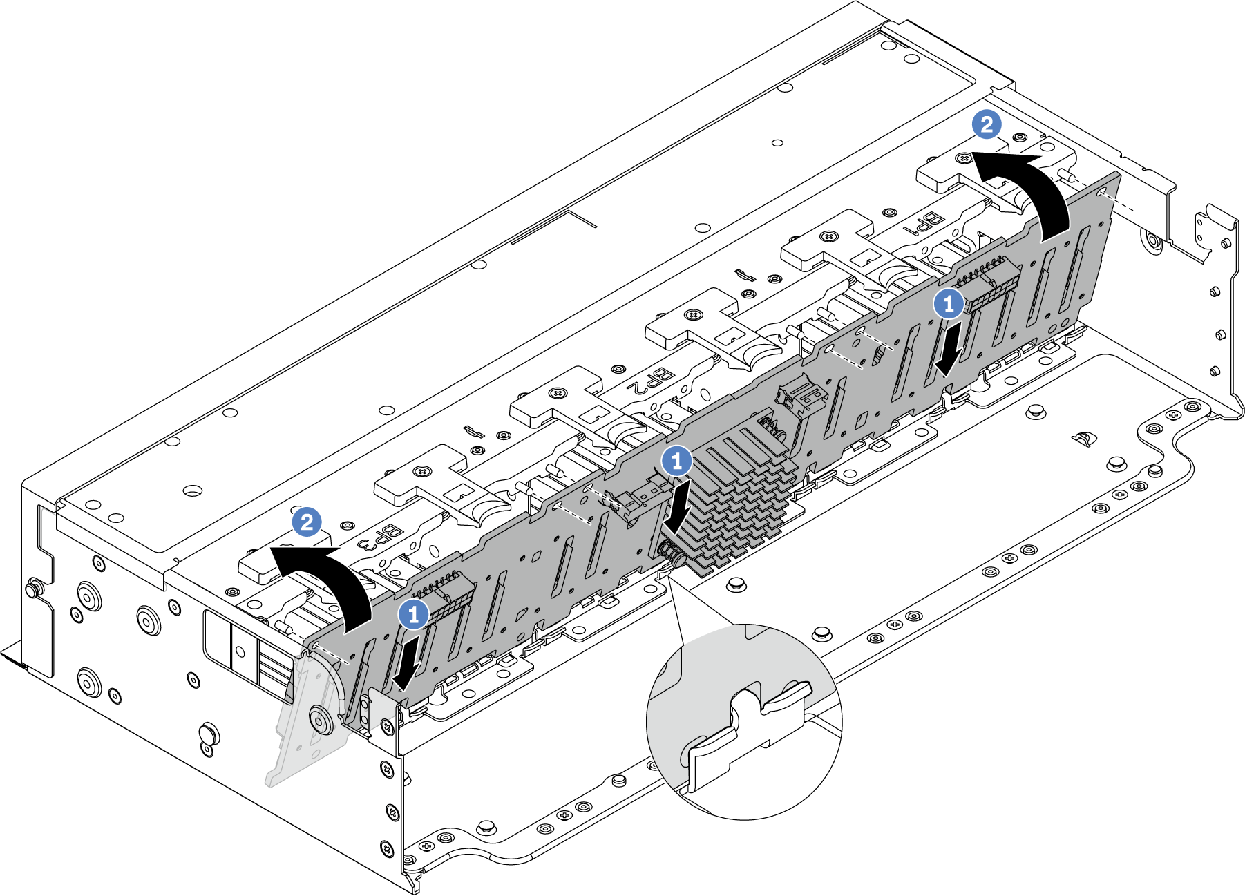
 Align the bottom of the backplane with the slots on the chassis, and lower the backplane into the chassis.
 Rotate the backplane to the vertical position. Align the holes in the backplane with the pins on the chassis, and press the backplane into position. The release tabs will secure the backplane in place.
After you finish
Reinstall all the drives and fillers (if any) into the drive bays. See Install a hot-swap drive.
Reinstall the fan cage. See Install the system fan cage.
Reinstall the air baffle if you have removed it. See Install the air baffle.
Complete the parts replacement. See Complete the parts replacement.
If you have installed an AnyBay backplane with U.3 NVMe drives for Trimode, enable U.3 x1 mode for the selected drive slots on the backplane through the XCC Web GUI. See U.3 NVMe drive can be detected in NVMe connection, but cannot be detected in Tri-mode.
Demo video