Install a CX-7 heat sink
Follow the instructions in this section to install a CX-7 heat sink. The procedure must be executed by a trained technician.
About this task
Attention
- Read Installation Guidelines and Safety inspection checklist to ensure that you work safely.
- Power off the server and peripheral devices and disconnect the power cords and all external cables. See Power off the server.
- Prevent exposure to static electricity, which might lead to system halt and loss of data, by keeping static-sensitive components in their static-protective packages until installation, and handling these devices with an electrostatic-discharge wrist strap or other grounding system.
Important
Putty pad/phase change material (PCM) replacement guidelines
- Before replacing the putty pad/PCM, gently clean the hardware surface with an alcohol cleaning pad.
- Hold the putty pad/PCM carefully to avoid deformation. Make sure no screw hole or opening is blocked by the putty pad/PCM.
- Do not use expired putty pad/PCM. Check the expiry date on putty pad/PCM package. If the putty pads/PCM are expired, acquire new ones to properly replace them.
Note
Make sure you have the required tools listed below available to properly replace the component:
- Torx T15 bit
- Torque screwdriver
- Alcohol cleaning pad
- SR675 V3 CX-7 heat sink putty pad kit
Procedure
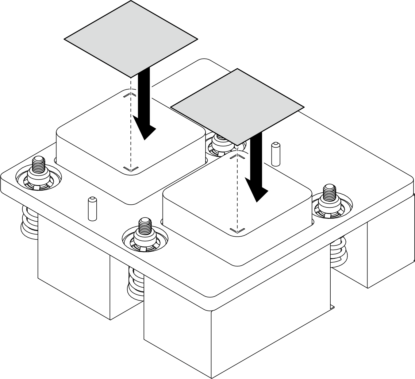
- Align the two putty pads with the markings on the bottom of the CX-7 heat sink, and attach them to the CX-7 heat sink.Figure 1. Putty pad application
- Install the CX-7 heat sink.
 Orient the CX-7 heat sink so that the arrow symbol on the CX-7 heat sink label faces toward the cable connectors on the CX-7 mezz board; then, gently place the CX-7 heat sink onto the CX-7 mezz board.
 Fasten the four Torx T15 screws in the installation sequence shown on the CX-7 heat sink label.NoteLoosen or tighten the screws with a torque screwdriver set to the proper torque. For reference, the torque required for the screws to be fully loosen or tighten is 0.5±0.1 newton-meters, 4.5±0.5 inch-pounds.Figure 2. CX-7 heat sink installation
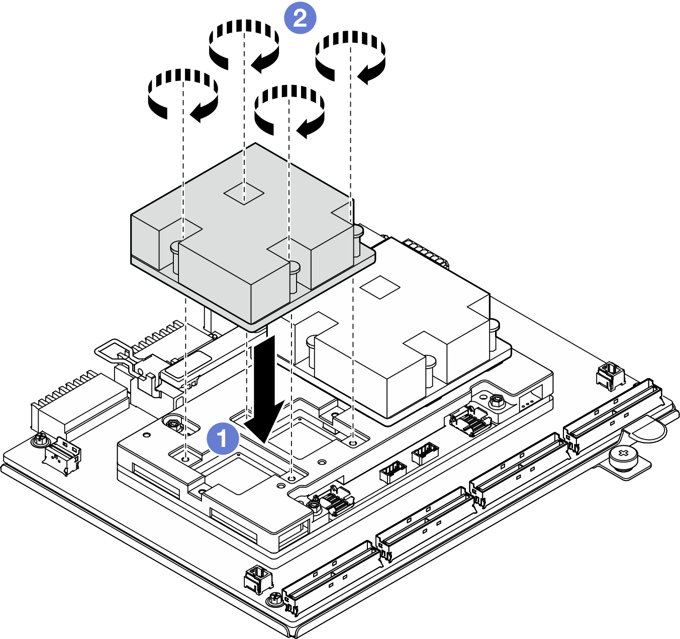
After you finish
- Reinstall the CX-7 assembly. See Install the CX-7 assembly.
- Reconnect the cables to the CX-7 carrier board and the CX-7 mezz board. See CX-7 carrier board cable routing and OSFP port card cable routing for more information.CAUTION
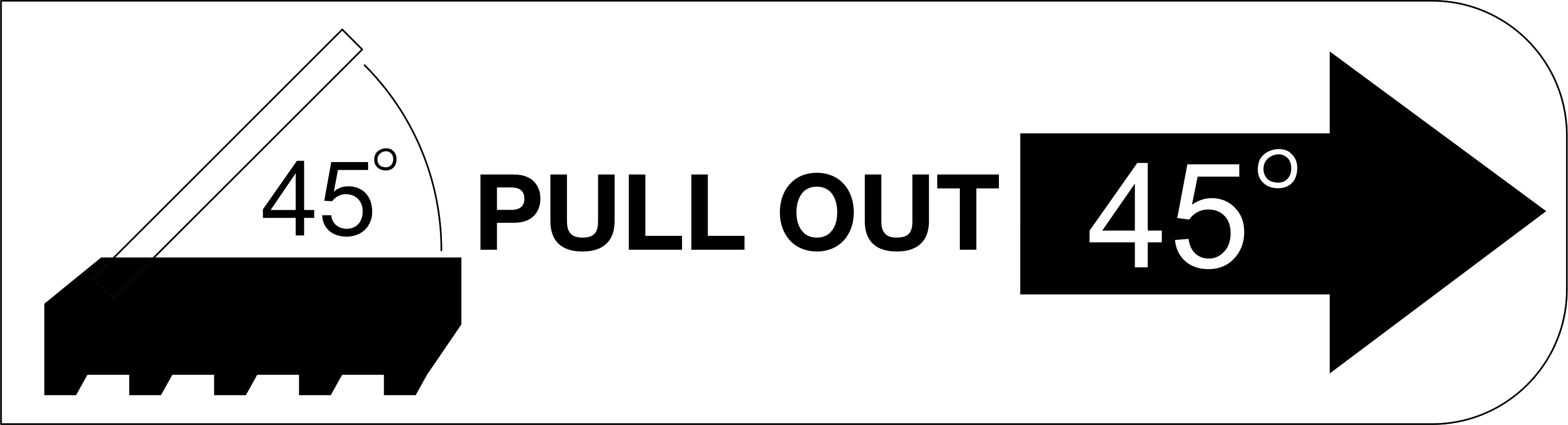
- Hold the cable connector at 45 degree angle when inserting it into the port.
- Have extremely precaution when reseating the connectors that have a 45 degree label on them as they are fragile and will get damage if not installed in the correct 45 degree angle.
- Complete the parts replacement. See Complete the parts replacement.
Demo video
Give documentation feedback