Remove an H100/H200 GPU and heat sink module
Follow instructions in this section to remove an H100/H200 GPU and heat sink module. The procedure must be executed by a trained technician.
About this task
Attention
- Read Installation Guidelines and Safety inspection checklist to ensure that you work safely.
- Power off the server and peripheral devices and disconnect the power cords and all external cables. See Power off the server.
- Two people and one lifting device on site that can support up to 400 lb (181 kg) are required to perform this procedure. If you do not already have a lifting device available, Lenovo offers the Genie Lift GL-8 material lift that can be purchased at Data Center Solution Configurator. Make sure to include the Foot-release brake and the Load Platform when ordering the Genie Lift GL-8 material lift.
- Make sure to inspect the connectors and sockets on the GPU and the GPU baseboard. Do not use the GPU or the GPU baseboard if its connectors are damaged or missing, or if there are debris in the sockets. Replace the GPU or the GPU baseboard with a new one before continuing the installation procedure.
- GPU and heat sink is one part. Do not remove the heat sink from the GPU.
- The following table shows the mapping information about the physical GPU sockets, slot numbering in XCC, and module IDs in nvidia-smi.
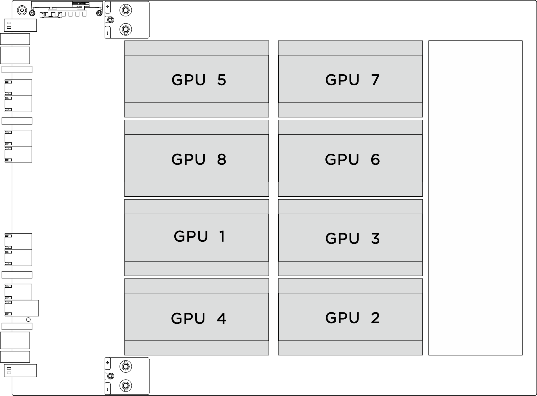
Physical GPU socket Slot numbering in XCC Module ID in nvidia-smi SXM 1 Slot 21 1 SXM 2 Slot 24 2 SXM 3 Slot 22 3 SXM 4 Slot 23 4 SXM 5 Slot 17 5 SXM 6 Slot 20 6 SXM 7 Slot 18 7 SXM 8 Slot 19 8
Note
Make sure you have the required tools listed below available to properly replace the component:
- Torque screwdriver which can be set to 0.6 newton-meters, 5.3 inch-pounds
- Torx T15 extended bit (200 mm long)
- H100/H200 jig
Procedure
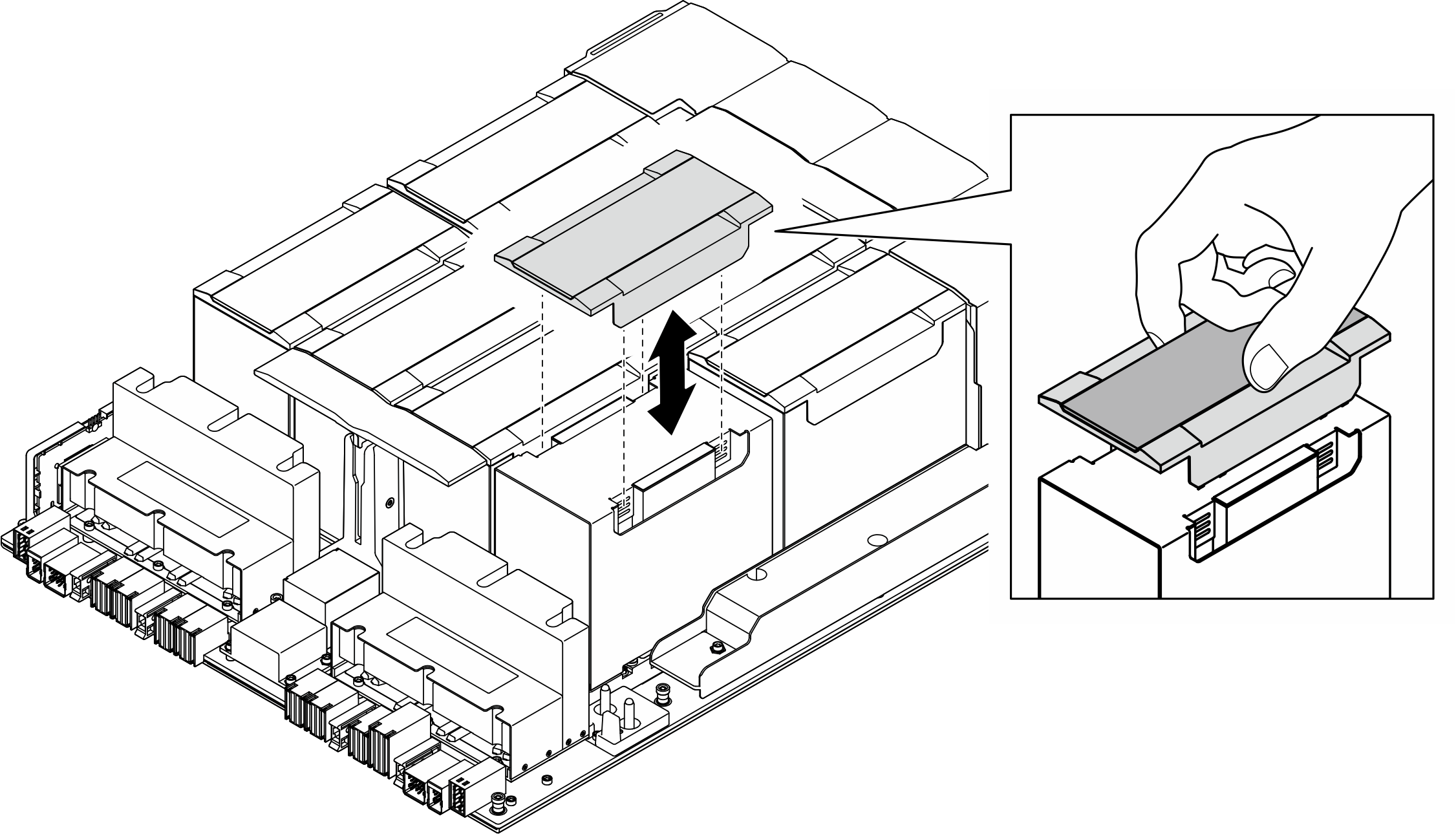
- Remove the plastic cover from the GPU and heat sink module.Figure 1. Plastic cover removal
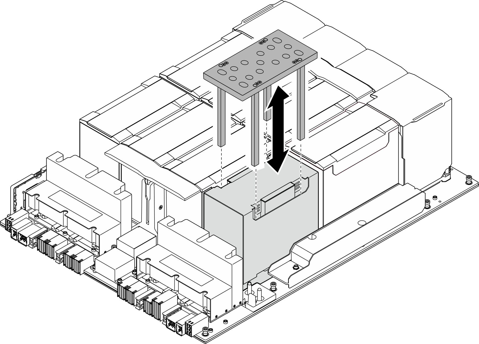
- Align the jig with the GPU heat sink and carefully install it onto the GPU heat sink.Figure 2. Jig installation
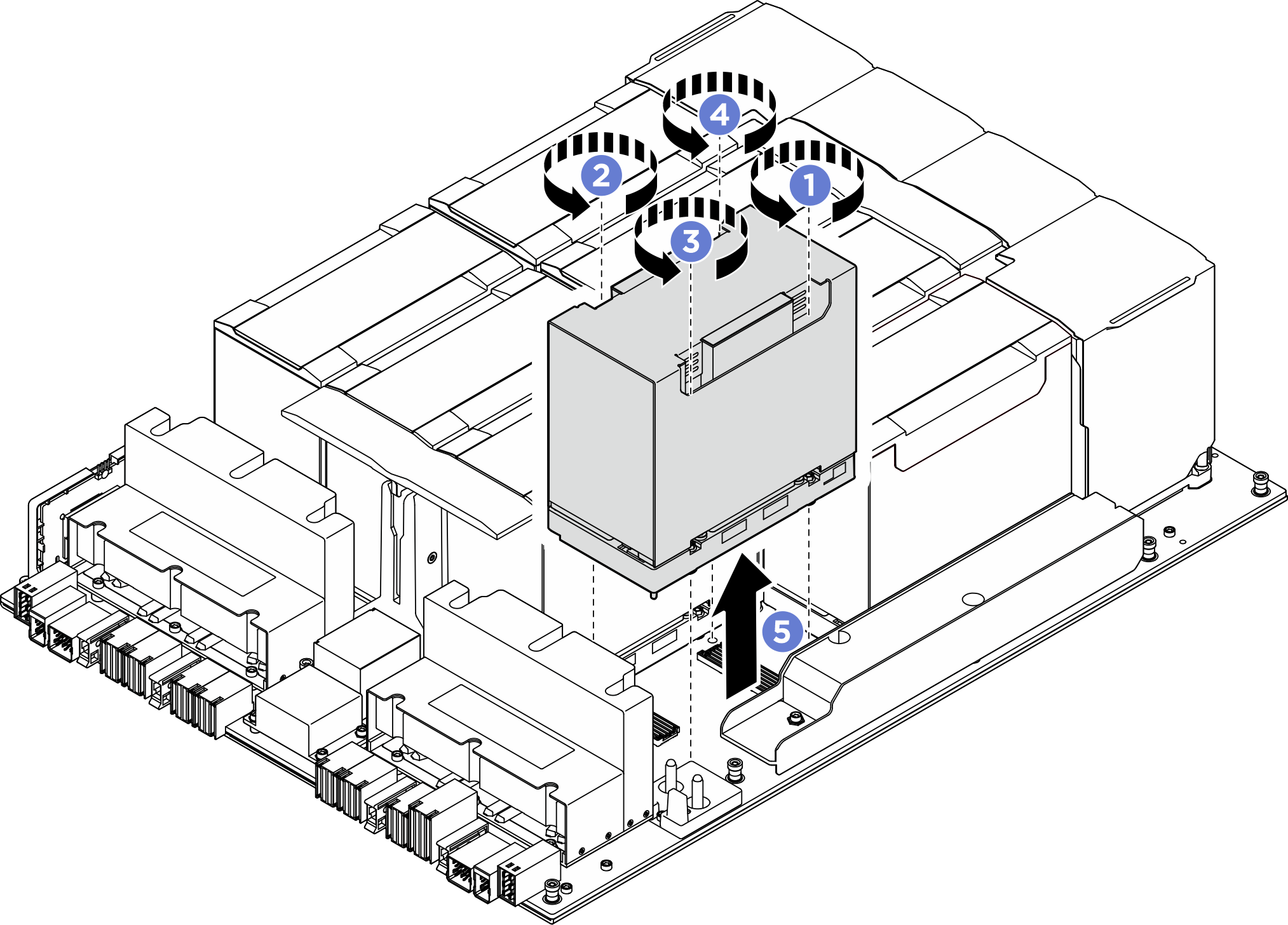
- Insert the torque screwdriver into the designated holes on the jig, and loosen the four Torx T15 screws in the sequence shown in the illustration below (
 >
>  >
>  >
>  ).NoteLoosen screws with a torque screwdriver set to the proper torque. For reference, the torque required for the screws to be fully loosen is 0.6 newton-meters, 5.3 inch-pounds.Figure 3. Screw removal
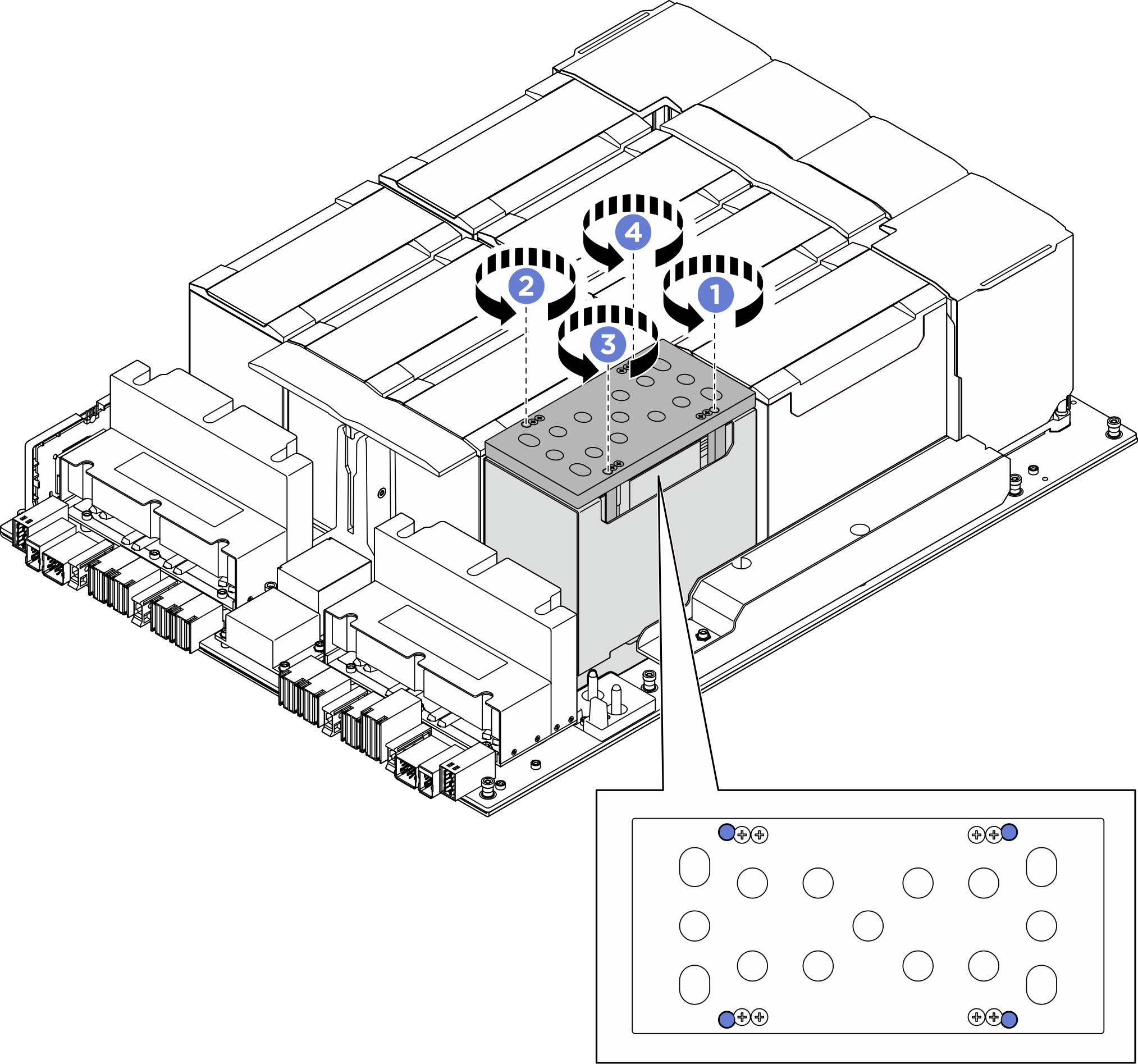
- Remove the jig from the GPU heat sink.Figure 4. Jig removal
- Use both hands to lift the GPU and heat sink module out of the GPU baseboard.Figure 5. GPU and heat sink module removal
After you finish
If you are instructed to return the component or optional device, follow all packaging instructions, and use any packaging materials for shipping that are supplied to you.
Give documentation feedback