Remove the system I/O board or processor board
Follow instructions in this section to remove the system I/O board or processor board. The procedure must be executed by a trained technician.
About this task
Important
- This task must be operated by trained technicians that are certified by Lenovo Service. Do not attempt to remove or install it without proper training and qualification.
- When removing the memory modules, label the slot number on each memory module, remove all the memory modules from the system board assembly, and set them aside on a static-protective surface for reinstallation.
- When disconnecting cables, make a list of each cable and record the connectors the cable is connected to, and use the record as a cabling checklist after installing the new system board assembly.
Attention
- Read Installation Guidelines and Safety inspection checklist to ensure that you work safely.
- Power off the server and peripheral devices and disconnect the power cords and all external cables. See Power off the server.
Note
Make sure you have the required tools listed below available to properly replace the component:
- Phillips #1 screwdriver
- Phillips #2 screwdriver
- 5 mm hex socket screwdriver bit
- 7 mm hex socket screwdriver bit
Procedure
- Remove the two cable guides.
- Unfasten the six screws to lift the cable guide out of the 2U compute shuttle.Figure 1. Cable guide removal
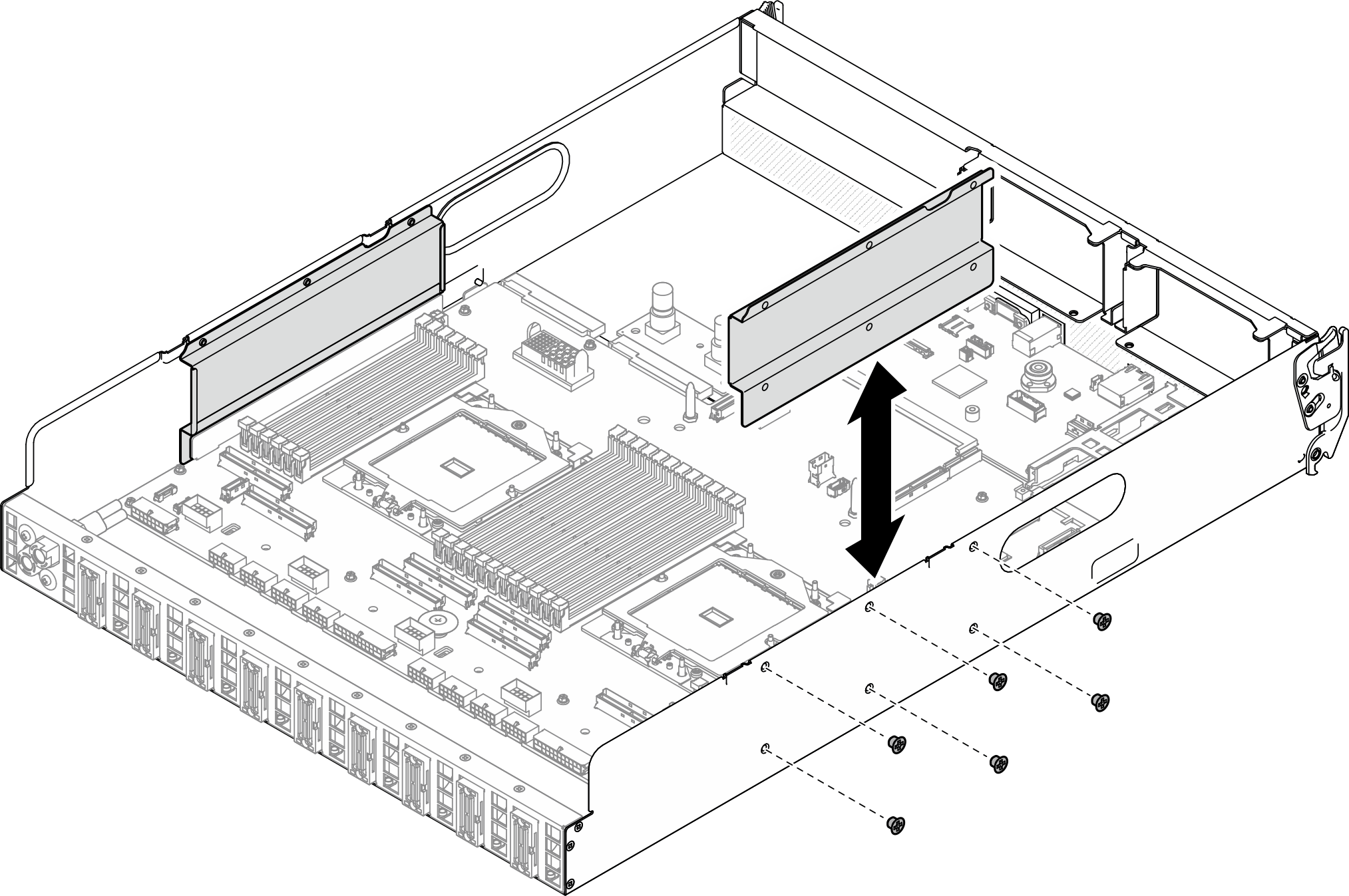
- Unfasten the six screws to lift the cable guide out of the 2U compute shuttle.
- Disengage the system board assembly.
 Pull up the rear lifting handle to release the system board assembly.
 Grasp both lifting handles and slide the system board assembly toward the front of the 2U compute shuttle.NoteThe two lifting handles only serve the purpose of removing system board assembly. Do not attempt to lift the whole
2U compute shuttle with them. Figure 2. System board assembly disengagement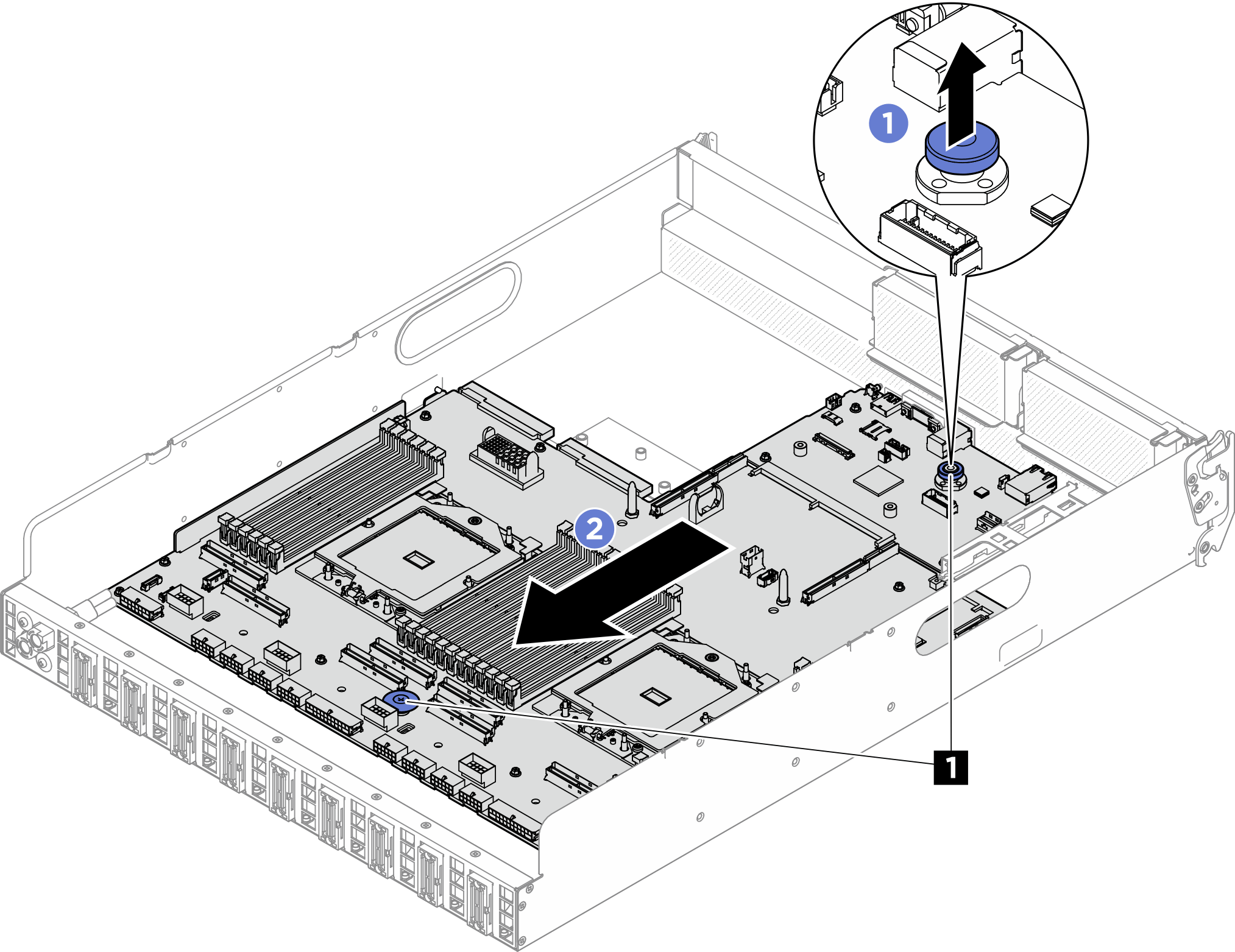
1 Lifting handles
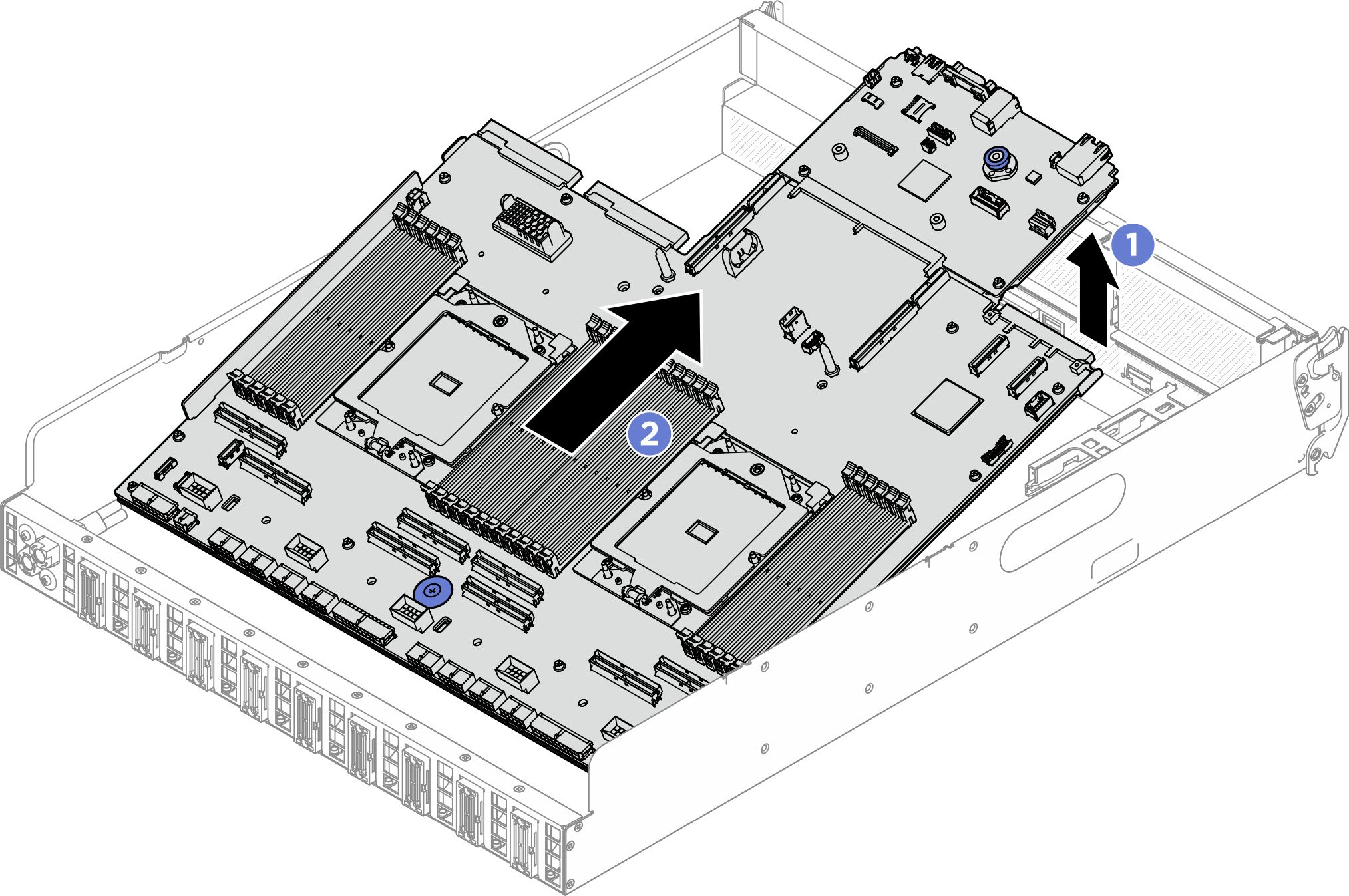
- Remove the system board assembly.
- Tilt the system board assembly so that its rear end is up.
- Hold both lifting handles, and lift the system board assembly out of the 2U compute shuttle.Figure 3. System board assembly removal
- Remove the system I/O board from the processor board.
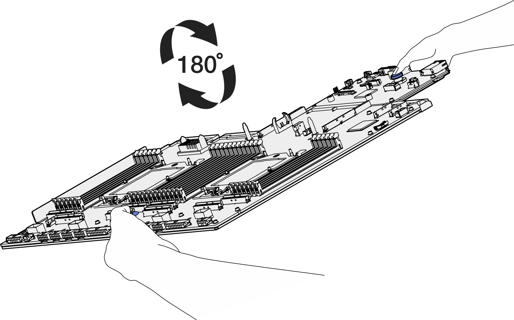
- Separate the system board assembly from the supporting sheet metal.
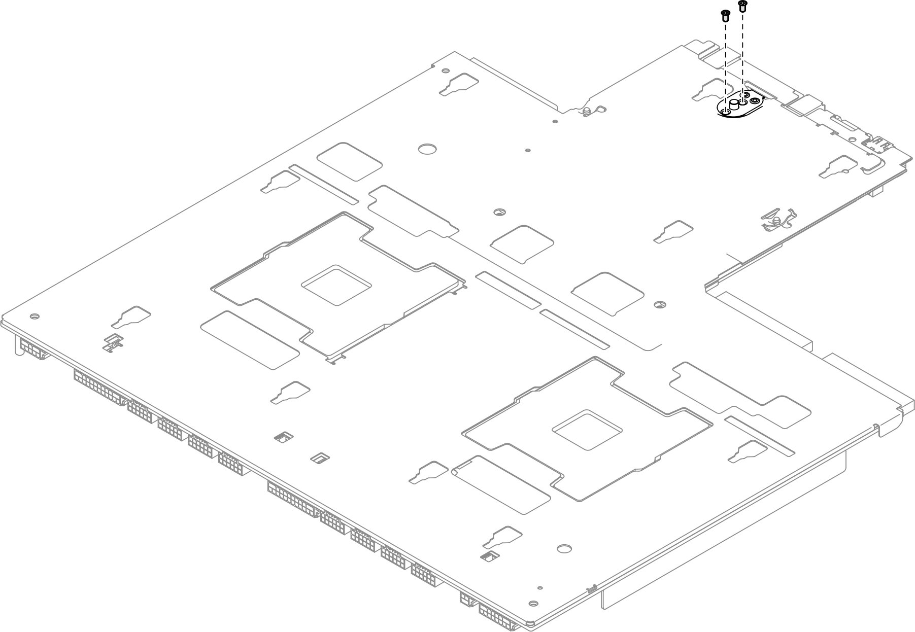
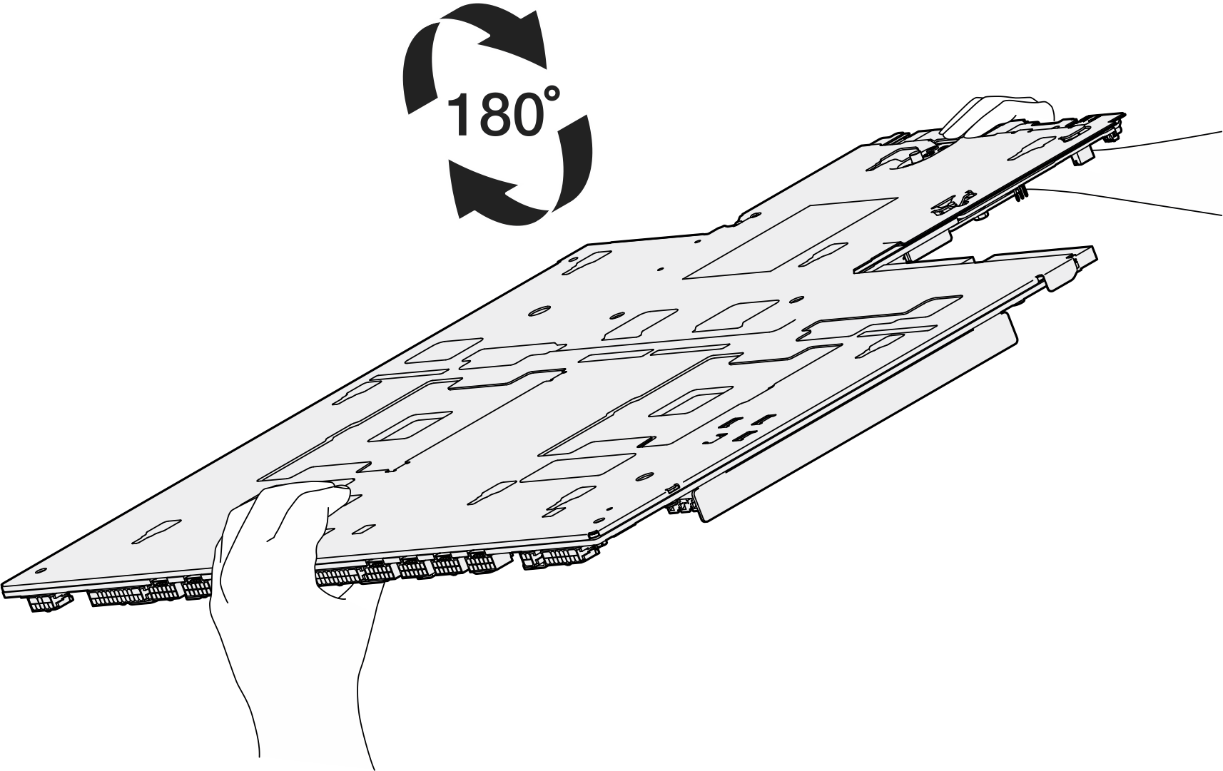
- Hold the two lifting handles, and carefully turn the system board assembly upside down.Figure 4. Turning the system board assembly upside down
- Use a Phillips #1 screwdriver to remove the two screws from the bottom of the supporting sheet metal.Figure 5. Screw removal
- Hold the two lifting handles, and carefully turn the system board assembly right-side up.Figure 6. Turning the system board assembly right-side up
- Remove the following components from the system board assembly as illustrated:
- Use a 5 mm hex socket with a screwdriver to remove the two hex nuts.
- Use a 7 mm hex socket with a screwdriver to remove the two guide pins.
- Use a Phillips #2 screwdriver to remove the lifting handle.
- Use a Phillips #1 screwdriver to remove the fifteen screws
Figure 7. Component removal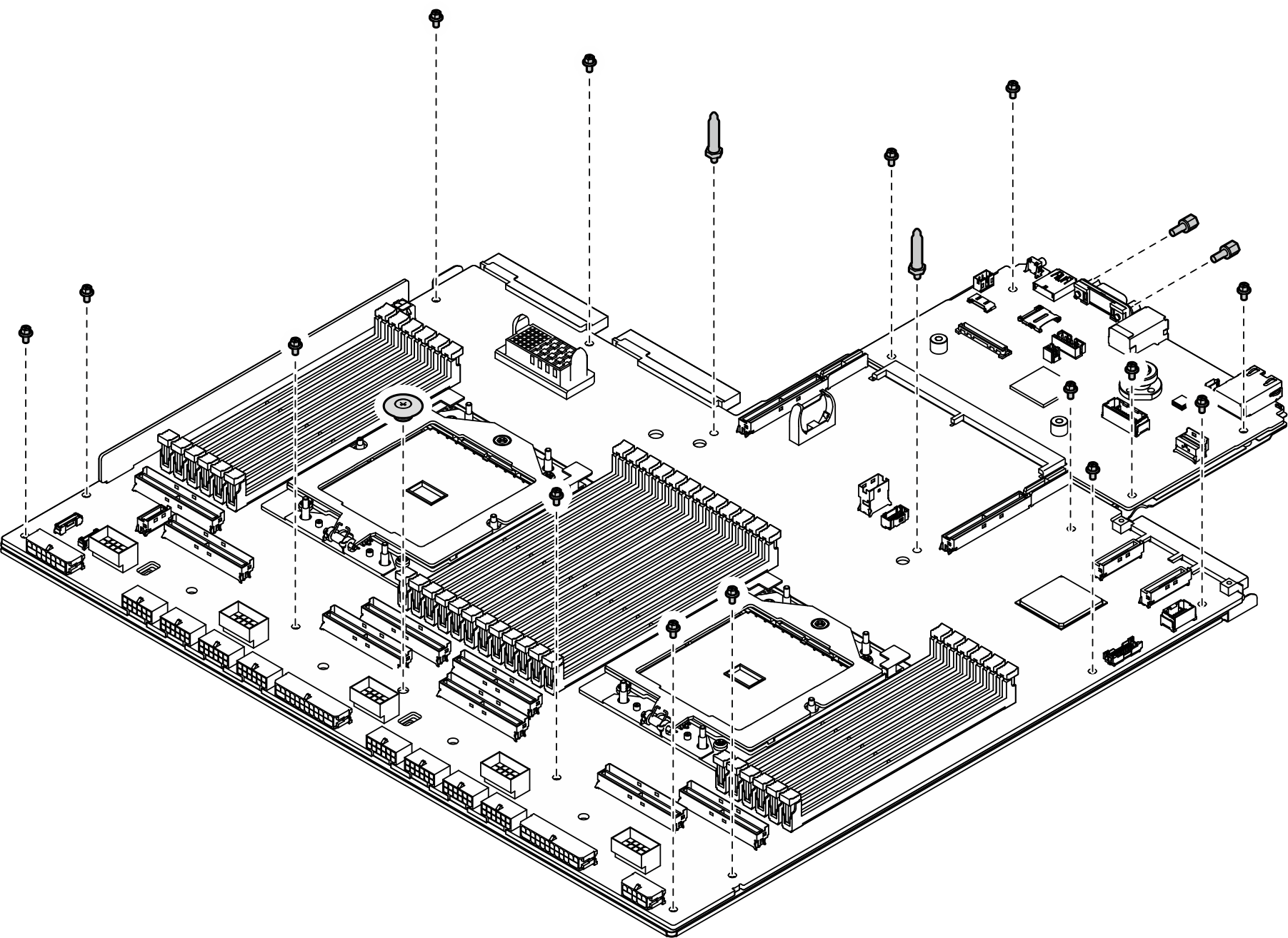
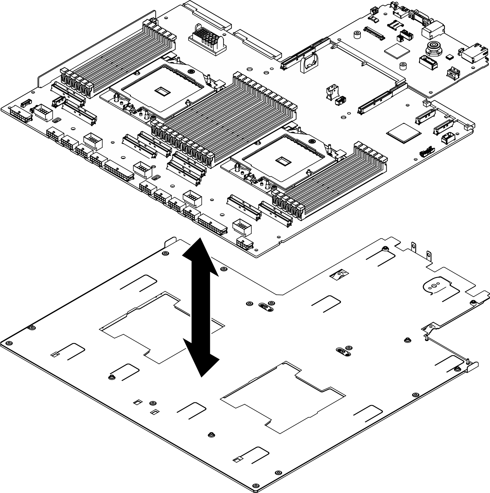
- Separate the system board assembly from the supporting sheet metal.Figure 8. System board assembly disassembly
- Hold the two lifting handles, and carefully turn the system board assembly upside down.
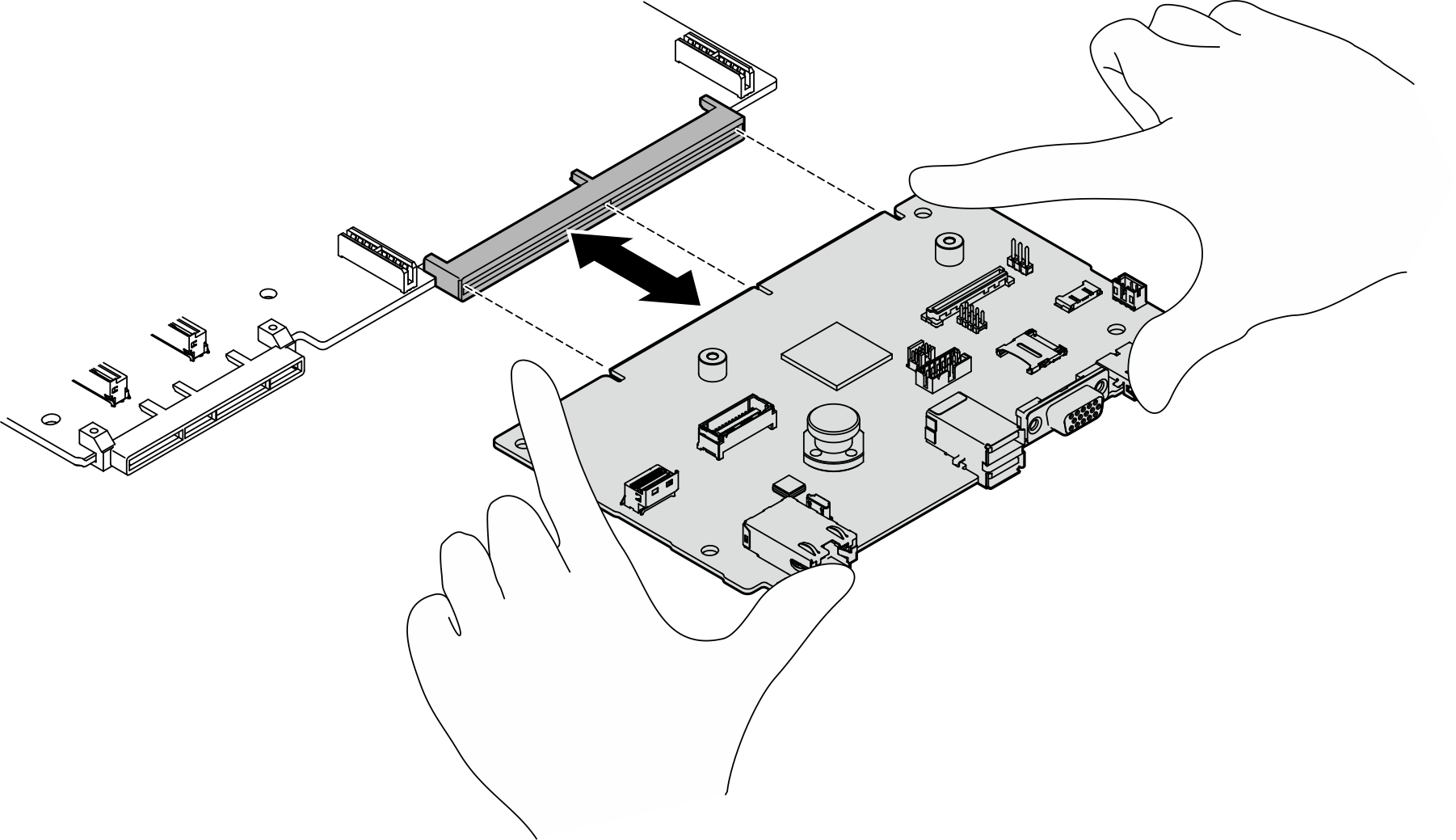
- Grasp the system I/O board by its edges, and carefully pull it out of the processor board.Figure 9. System I/O board removal
- Separate the system board assembly from the supporting sheet metal.
After you finish
If you are instructed to return the component or optional device, follow all packaging instructions, and use any packaging materials for shipping that are supplied to you.
Important
Before you return the processor board, make sure that you install the processor socket covers from the new processor board. To replace a processor socket cover:
- Take a socket cover from the processor socket assembly on the new processor board and orient it correctly above the processor socket assembly on the removed processor board.
- Gently press down the socket cover legs to the processor socket assembly, pressing on the edges to avoid damage to the socket pins. You might hear a click on the socket cover when it is securely attached.
- Make sure that the socket cover is securely attached to the processor socket assembly.
Give documentation feedback