Install the system I/O board or processor board
Follow instructions in this section to install the system I/O board or processor board. The procedure must be executed by a trained technician.
About this task
Important
Removing and installing this component requires trained technicians. Do not attempt to remove or install it without proper training.
Attention
- Read Installation Guidelines and Safety inspection checklist to ensure that you work safely.
- Touch the static-protective package that contains the component to any unpainted metal surface on the server; then, remove it from the package and place it on a static-protective surface.
Note
Make sure you have the required tools listed below available to properly replace the component:
- Phillips #1 screwdriver
- Phillips #2 screwdriver
- 5 mm hex socket screwdriver bit
- 7 mm hex socket screwdriver bit
Firmware and driver download: You might need to update the firmware or driver after replacing a component.
Go to Drivers and Software download website for ThinkSystem SR685a V3 to see the latest firmware and driver updates for your server.
Go to Update the firmware for more information on firmware updating tools.
Procedure
- Depending on the needs, do one of the following:
- If you are going to replace the system I/O board and reuse the processor board, install a new system I/O board onto the processor board.
- If you are going to replace the processor board and reuse the system I/O board, install the existing system I/O board onto a new processor board.
- Install the system I/O board onto the processor board.
- Align the system I/O board with the connector on the processor board, and use both hands to push the system I/O board and slightly insert it into the connector.NoteTo prevent the contact of the system I/O board from damage, ensure that the system I/O board is aligned correctly with the connector on the processor board, and remains as horizontal as possible during the insertion.Figure 1. System I/O board installation
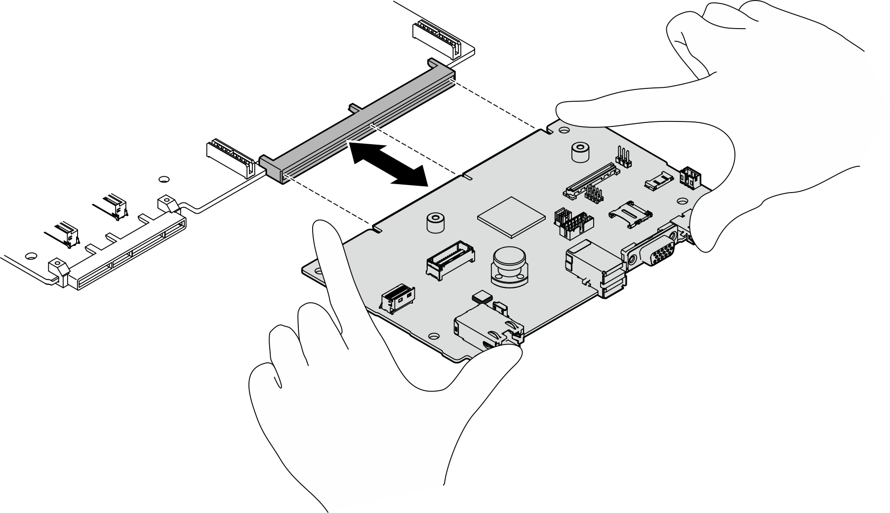
- Align the system I/O board with the connector on the processor board, and use both hands to push the system I/O board and slightly insert it into the connector.
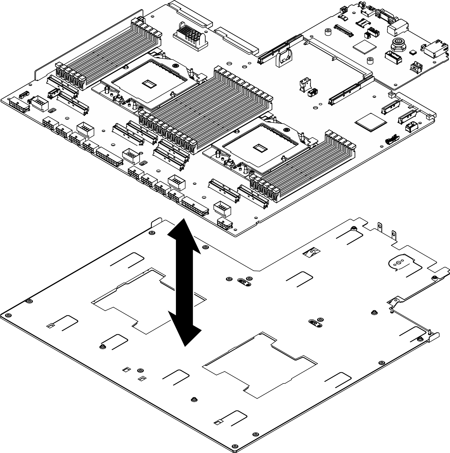
- Install the system board assembly to the supporting sheet metal.
- Lower the system board assembly into the supporting sheet metal.Figure 2. System board assembly installation
- Install the following components to the system board assembly as illustrated:
- Use a 5 mm hex socket with a screwdriver to install the two hex nuts.
- Use a 7 mm hex socket with a screwdriver to install the two guide pins.
- Use a Phillips #2 screwdriver to install the lifting handle.
- Use a Phillips #1 screwdriver to install the fifteen screws.
Figure 3. Component installation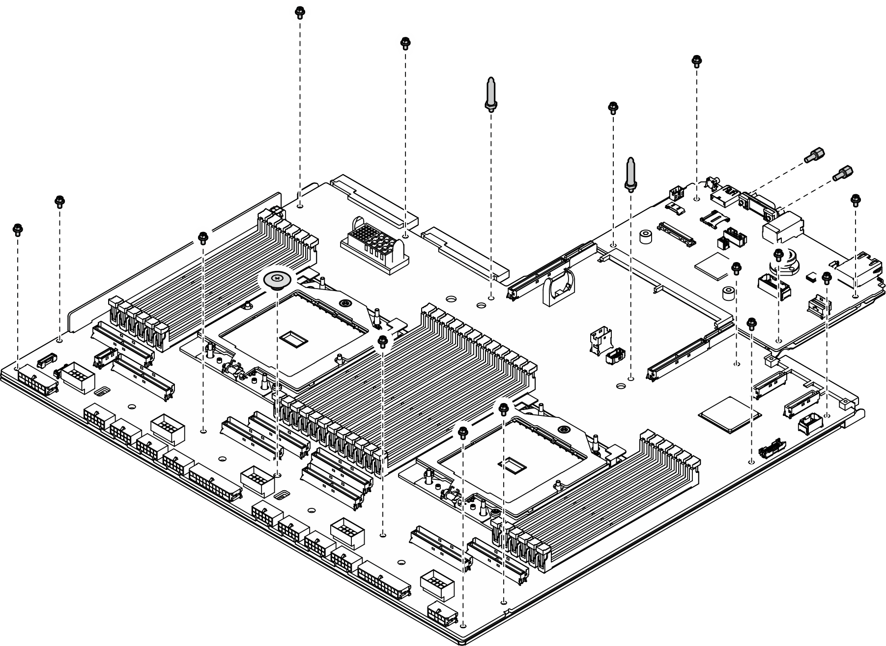
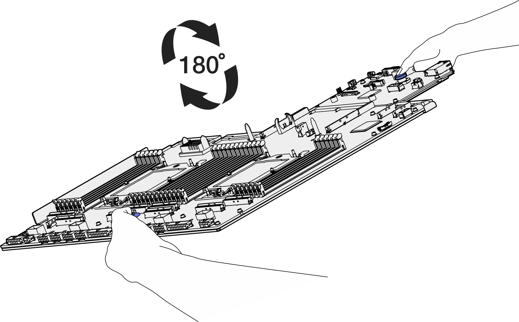
- Hold the two lifting handles, and carefully turn the system board assembly upside down.Figure 4. Turning the system board assembly upside down
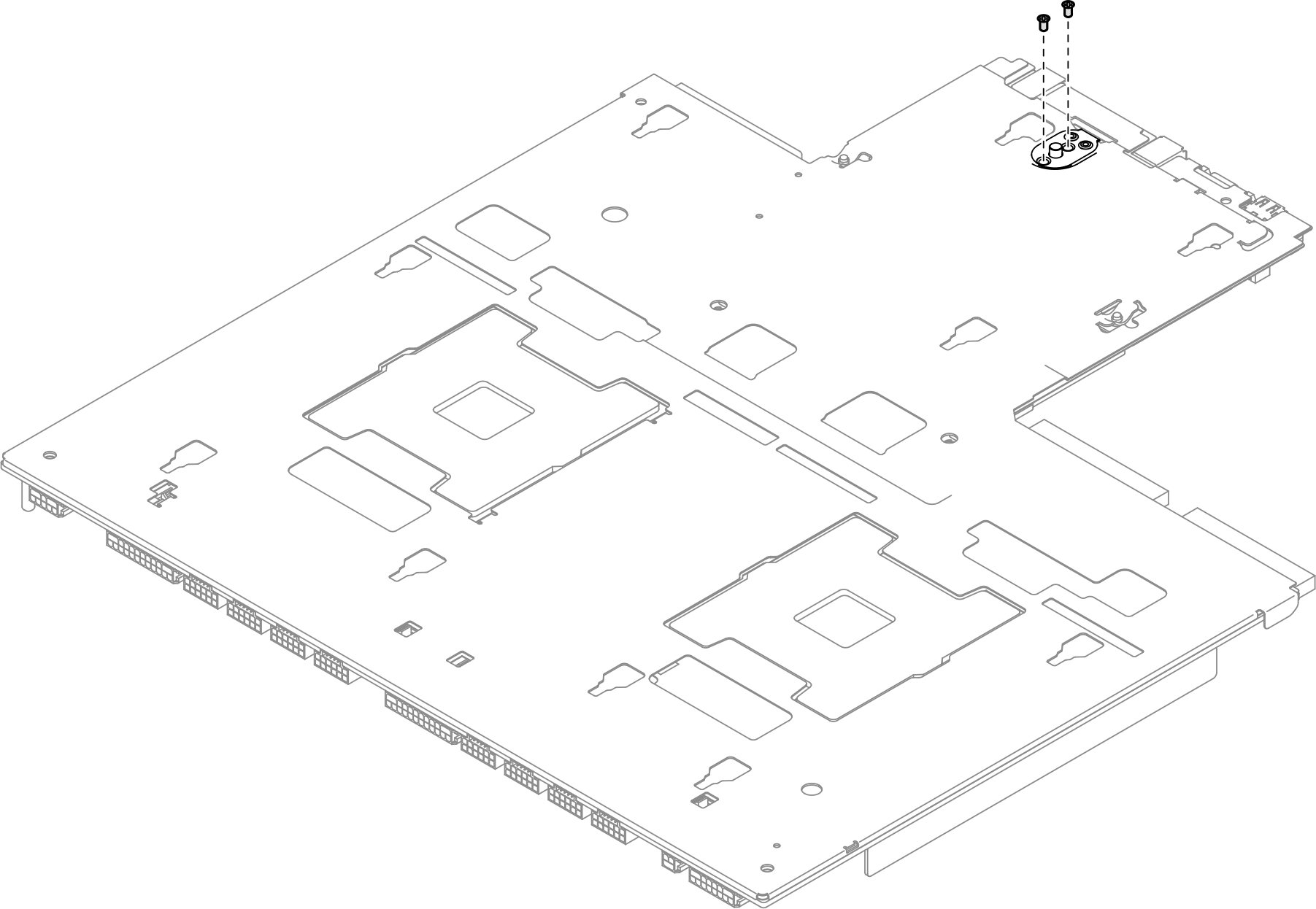
- Use a Phillips #1 screwdriver to fasten the two screws on the bottom of the supporting sheet metal.Figure 5. Screw installation
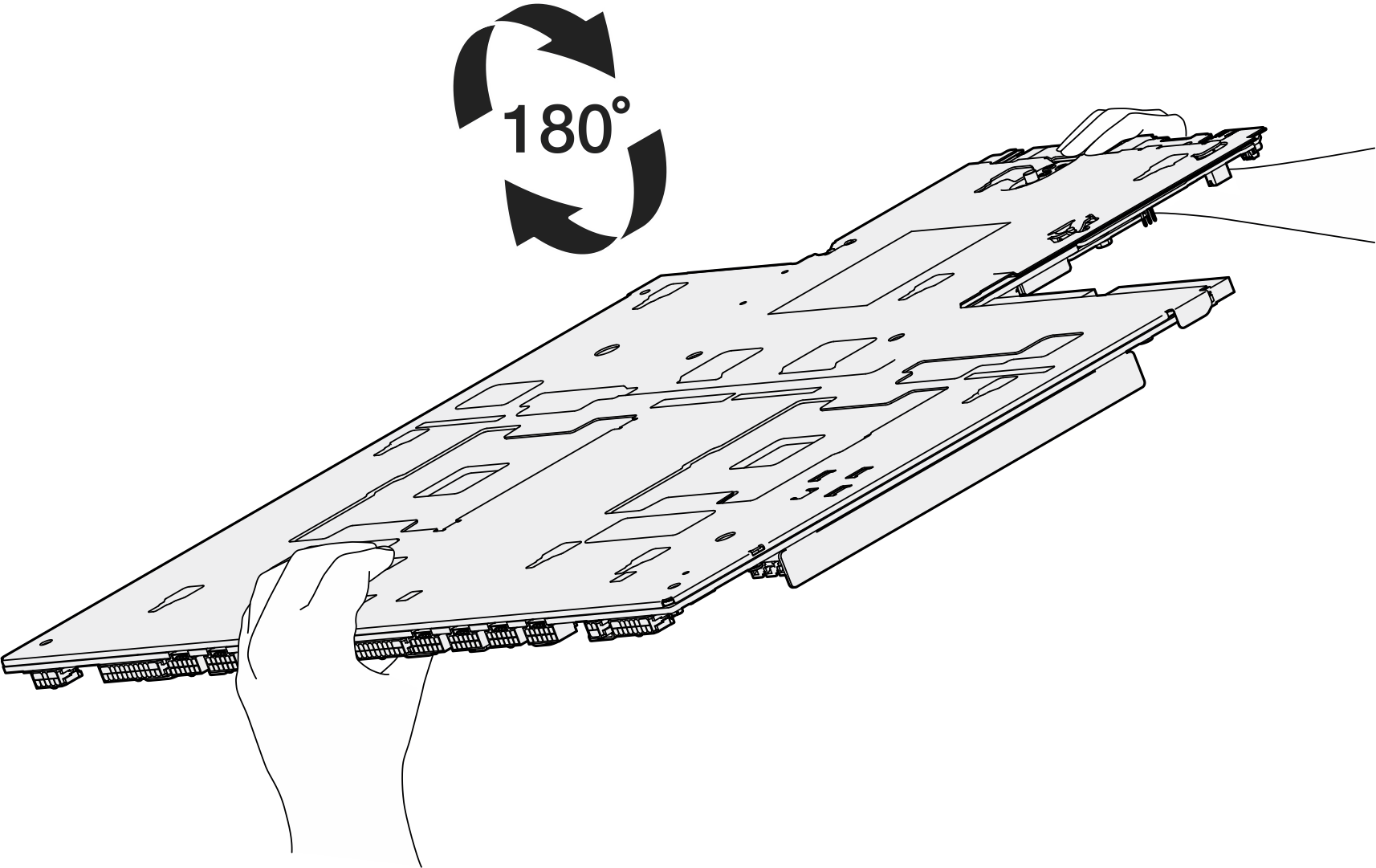
- Hold the two lifting handles, and carefully turn the system board assembly right-side up.Figure 6. Turning the system board assembly right-side up
- Lower the system board assembly into the supporting sheet metal.
- Place the system board assembly inside the 2U compute shuttle.
 Grasp the two lifting handles on the system board assembly, and tilt the system board assembly so that its rear end is up.
 Lower the system board assembly into the 2U compute shuttle.
Figure 7. System board assembly installation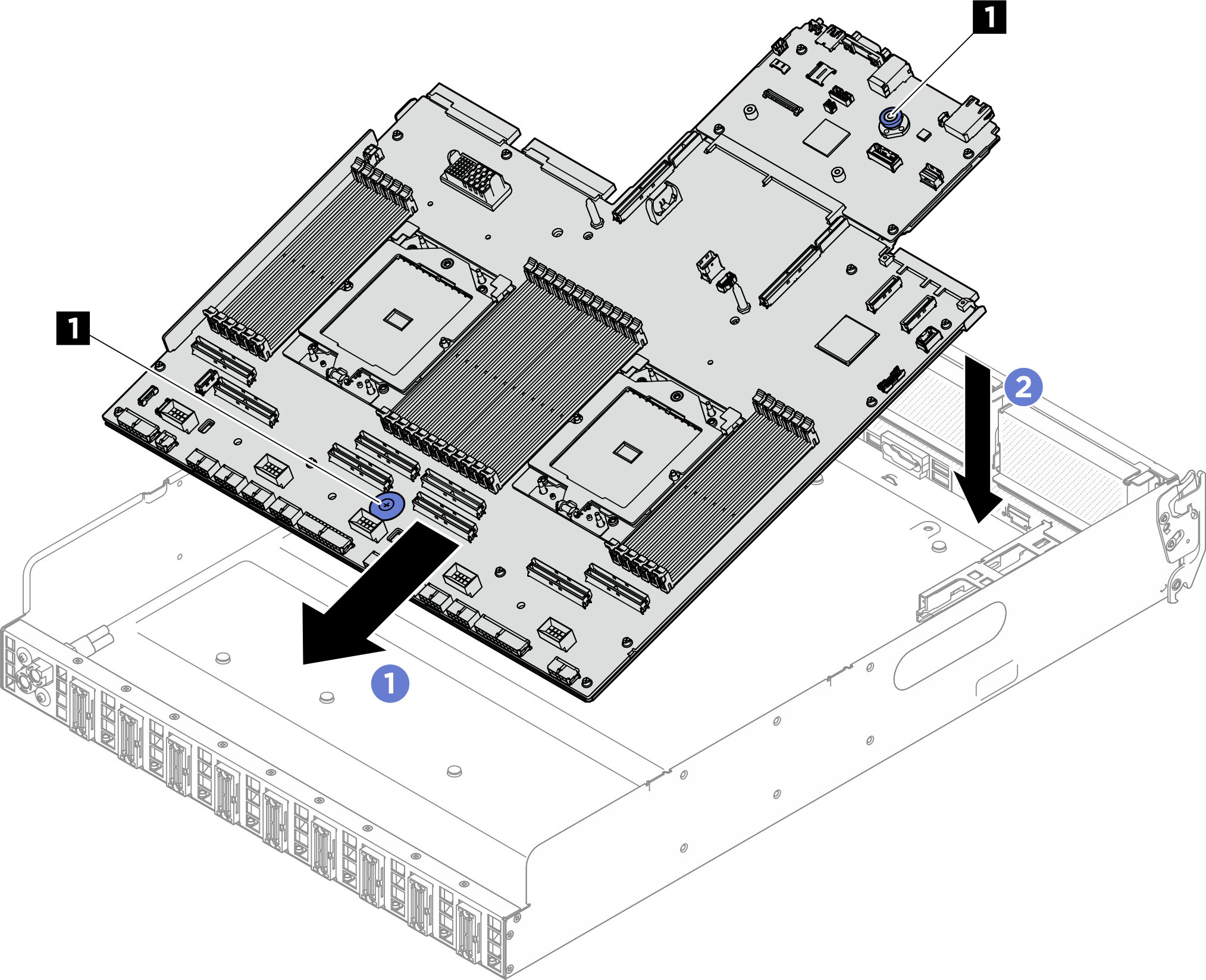
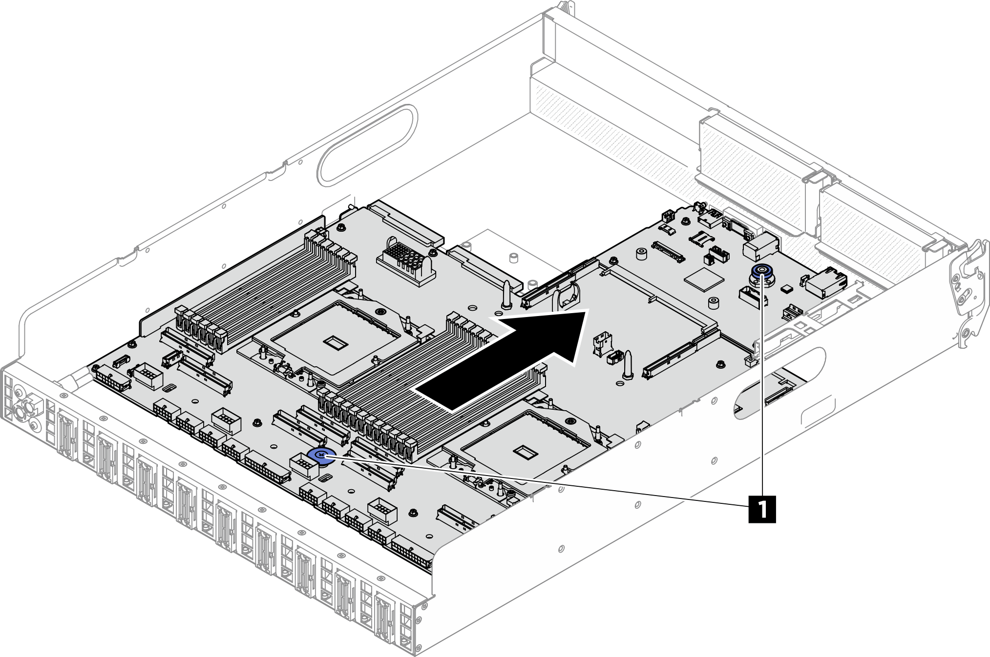
1 Lifting handles - Grasp the two lifting handles, and slide the system board assembly toward the rear of the 2U compute shuttle until it clicks into place. Make sure that the rear connectors on the new system board assembly are inserted into the corresponding holes in the rear panel.Figure 8. System board assembly installation
1 Lifting handles - Install the cable guides.
- Fasten the six screws to secure the cable guide to the 2U compute shuttle.Figure 9. Cable guide installation
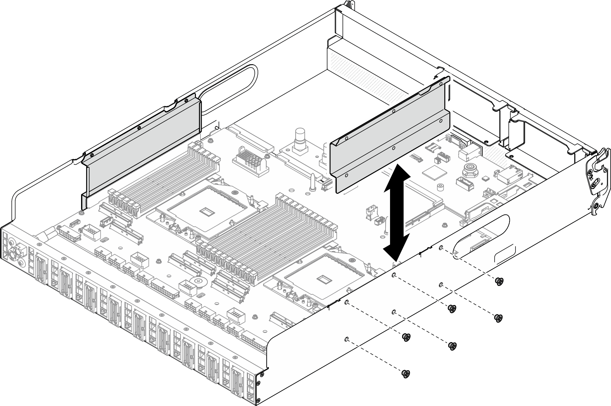
- Fasten the six screws to secure the cable guide to the 2U compute shuttle.
After you finish
- Reinstall the following components.
- If applicable, reinstall the OCP module. See Install the OCP module.
- If applicable, reinstall the PCIe riser assembly(ies). See Install a PCIe riser assembly.
- Reinstall each memory module to the same slot on the new system board assembly as on the defective system board assembly until all the memory modules are installed. See Install a memory module.
- Reinstall all the processors and the heat sinks. See Install a processor and Install a heat sink.
- Reinstall the processor air baffle. See Install the processor air baffle.
- Reconnect all the required cables to the same connectors on the system board assembly as the defective system board assembly.
- Ensure that all components have been reassembled correctly and that no tools or loose screws are left inside the server.
- Reinstall the 2U compute shuttle. See Install the 2U compute shuttle.
- Reconnect the power cords and any cables that you removed.
- Power on the server and any peripheral devices. See Power on the server.
- Reset the UEFI password if you set the password before. See Reset the UEFI password.
- Update the vital product data (VPD). See Update the Vital Product Data (VPD). Machine type number and serial number can be found on the ID label, see Identify the server and access the Lenovo XClarity Controller.
- Optionally, enable UEFI Secure Boot. See Enable UEFI Secure Boot.
Give documentation feedback