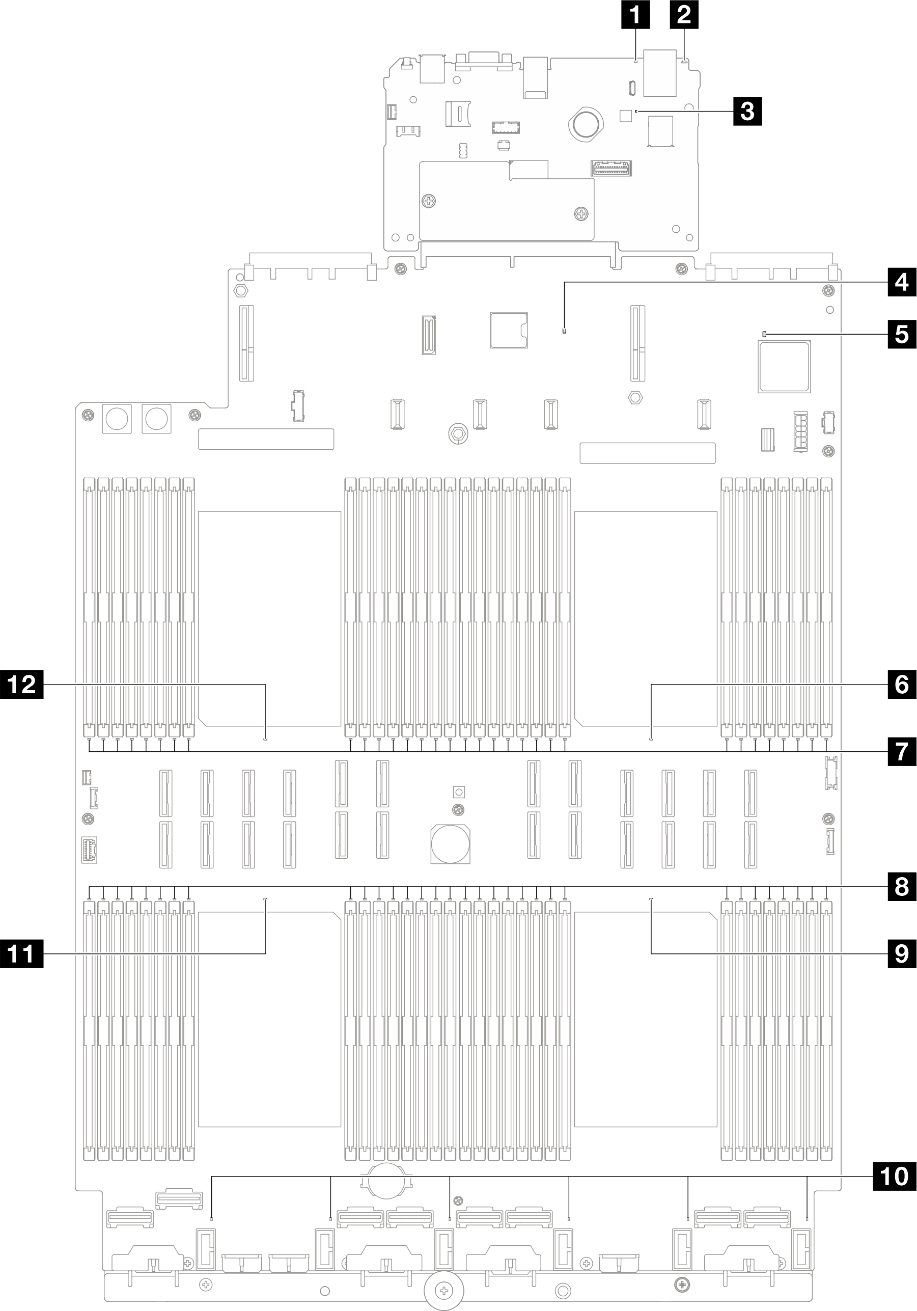
System-board-assembly LEDs
The following illustrations show the light-emitting diodes (LEDs) on the system board assembly.
Press the power button to light the LEDs on the system board assembly when the power source has been removed from the server.
| LED | Description | Action |
|---|---|---|
| 1 System error LED (yellow) | LED on: an error has been detected on the server. Causes might include one or more of the following errors:
| Check system logs or internal error LEDs to identify the failed part. |
| 2 System ID LED (blue) | This LED helps you to visually locate the server. | A system ID button with LED is also located on the front of the server. You can press the system ID button to turn on/off or blink the front and rear ID LEDs. |
| 3 XCC heartbeat LED (green) | The XCC heartbeat LED helps you identify the XCC status.
|
|
| 4 PCH heartbeat LED (green) | The PCH heartbeat LED helps you identify the PCH status.
| If the PCH heartbeat LED is always off or always on, do the following:
|
| 5 FPGA heartbeat LED (green) | The FPGA heartbeat LED helps you identify the FPGA status.
| If FPGA heartbeat LED is always off or always on, do the following:
|
| 6 Processor 1 error LED (Amber) | LED on: an error has occurred to the processor the LED represents. | Replace the processor. |
| 7 DIMM 1-32 error LEDs (Amber) | LED on: an error has occurred to the DIMM the LED represents. | For more information, see Memory problems. |
| 8 DIMM 33-64 error LEDs (Amber) | LED on: an error has occurred to the DIMM the LED represents. | For more information, see Memory problems. |
| 9 Processor 4 error LED (Amber) | LED on: an error has occurred to the processor the LED represents. | Replace the processor. |
| 10 Fan 1-6 error LED (Amber) | LED on: an error has occurred to the fan the LED represents. | Replace the fan. |
| 11 Processor 3 error LED (Amber) | LED on: an error has occurred to the processor the LED represents. | Replace the processor. |
| 12 Processor 2 error LED (Amber) | LED on: an error has occurred to the processor the LED represents. | Replace the processor. |