Replacing a microprocessor and heat sink
This information provides instructions on how to replace a microprocessor and heat sink.
To replace a microprocessor and heat sink, complete the following steps:
Attention: When you handle static-sensitive devices, take precautions to avoid damage from static electricity. For details about handling these devices, see Handling static-sensitive devices.
Note
- Use the microprocessor installation tool that came with the new microprocessor kit to remove the microprocessor from the server.
- Be extremely careful when handling the microprocessor, the microprocessor socket contacts are very fragile.
- Do not allow the thermal grease on the microprocessor and heat sink to come in contact with anything. Contact with any surface can compromise the thermal grease and the microprocessor socket.
- Do not touch the microprocessor contacts. Contaminants on the microprocessor contacts, such as oil from your skin, can cause connection failures between the contacts and the socket.
- Be sure to only install microprocessors that have the same speed, number of cores, and frequency.
- Each microprocessor socket must always contain either a socket cover or a microprocessor and heat sink.
- Be sure to use only the microprocessor installation tool provided with the new microprocessor to remove or install the microprocessor. Do not use other tools.
- The microprocessor installation tool has the microprocessor installed on the tool, and might have a protective cover over the microprocessor. Do not use the tool or remove the cover from the microprocessor until you are instructed to do so.
- The server supports up to four (per 4U server) Intel Xeon dual-core or quad-core microprocessors (one microprocessor on each compute book). See the Lenovo ServerProven website for a list of supported microprocessors.
- Install the microprocessor:
- Make sure that the microprocessor socket levers and retainer are in the open position.
- Open the packaging that contains the new microprocessor kit.
- Carefully remove the microprocessor installation tool assembly from the package.Attention
- The microprocessor FRU comes with two microprocessor tools: one tool is empty and one tool comes with a microprocessor and a cover on the bottom of the tool.
- Do not touch the microprocessor socket contacts. Contaminants on the microprocessor contacts, such as oil from your skin, can cause connection failures between the contacts and the socket.
- Handle the microprocessor carefully. Dropping the microprocessor during installation or removal can damage the contacts.
- Do not use excessive force when you press the microprocessor into the socket.
- Make sure that the microprocessor is oriented and aligned and positioned in the socket before you try to close the lever.
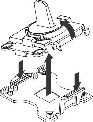
- Release the sides of the microprocessor protective cover on the bottom of the microprocessor and carefully remove the cover from the installation tool. The microprocessor is preinstalled on the installation tool.
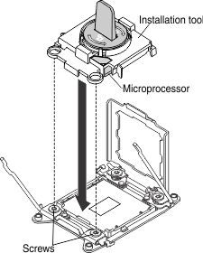
- Carefully align the microprocessor installation tool over the microprocessor socket. The microprocessor is keyed to ensure that the microprocessor is installed correctly.
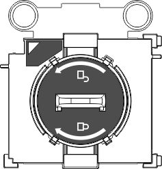
- Twist the handle on the microprocessor tool counterclockwise to the open position (as shown in the illustration) to insert the microprocessor into the socket. The microprocessor rests flush on the socket only if it is properly installed.
 Note
Note- Do not press the microprocessor into the socket.
- Do not touch the thermal grease on the bottom of the heat sink or on top of the microprocessor. Touching the thermal grease will contaminate it.
- Make sure that the microprocessor is oriented and aligned correctly in the socket before you close the microprocessor bracket frame.
- Lift the microprocessor installation tool from the socket.
- Remove the microprocessor dust cover.
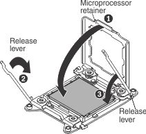
- Close the microprocessor retainer.
- Carefully close the microprocessor release levers to the closed position to secure the microprocessor in the socket. Make sure that you close the release lever on the left; then, close the release lever on the right.
- If you are installing a new heat sink, remove the plastic protective cover from the bottom of the heat sink. if you are reinstalling a heat sink that you removed earlier, make sure that the thermal grease is still on the bottom of the heat sink and on the top of the microprocessor.
Attention:
- If you are installing a new heat sink, do not set down the heat sink after you remove the plastic cover.
- Do not touch the thermal grease on the bottom of the heat sink. Touching the thermal grease will contaminate it.
- Position the heat sink over the microprocessor. The heat sink is keyed to assist with proper alignment.
- Align the screws on the heat sink with the holes on the heat sink retention module.
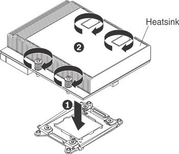
- Press firmly on the center of the heat sink, then press firmly on the captive screws and tighten them with a screwdriver, alternating between the screws in a figure-8 pattern, as indicated on the heat sink label. Rotate each screw one full rotation at a time. Repeat this process until the screws are tightened. You can damage the microprocessor if you tighten the screws on one side first, rather than alternating between screws. Do not over tighten the screws with excessive force.
- Reinstall the compute book cover (see Replacing the compute book cover).
- Reinstall the compute book into the server.
- Reconnect the power cords and any cables that you removed.
- Turn on the peripheral devices and the server.
Give documentation feedback