ConnectX-8 어댑터 라이저 어셈블리 제거
이 정보를 참조하여 ConnectX-8 어댑터 라이저 어셈블리를 제거하십시오.
이 작업 정보
필수 도구
T6 및 PH1 나사용 드라이버
Waterloop Miscellaneous Kit (SC750 V4) .
CX8 Conduction Plate
CX8 Gap Pad (ConnectX-8을 처음 설치하는 경우)
시스템은 아래 그림에 표시된 것과 같이 2가지 유형의 라이저 케이지(A/B가 인쇄된 1번, A/B/C/D가 인쇄된 2번)를 지원합니다. Connect-X 8 어댑터를 설치할 때는 2번 라이저 케이지를 사용해야 합니다.
그림 1. 라이저 케이지 유형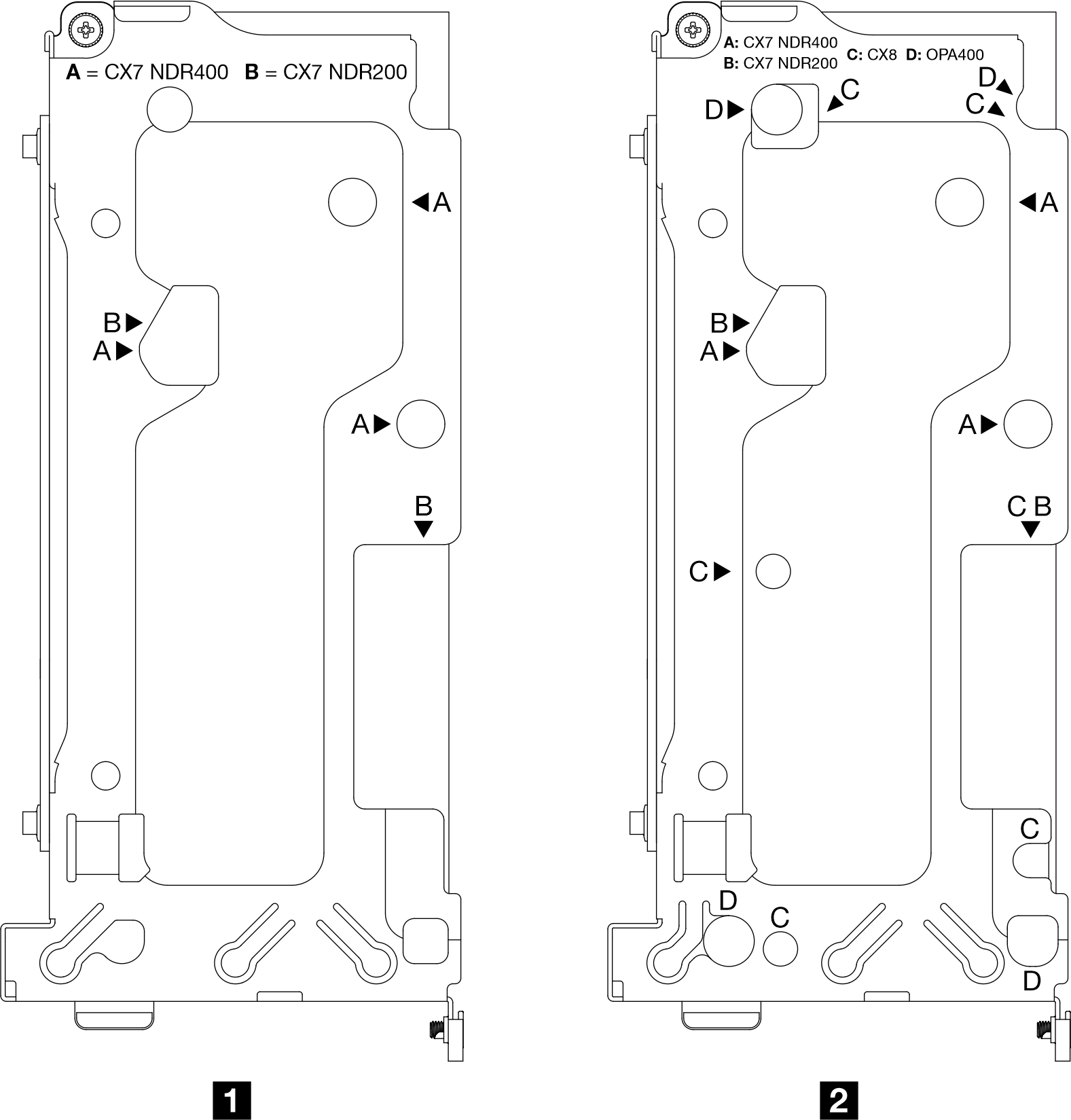
절차
- 워터 루프에서 ConnectX-8 라이저 어셈블리를 풉니다.
 라이저 어셈블리의 고정 나사를 푸십시오.
 C로 표시된 라이저 케이지의 나사 구멍에서 T6 나사 6개를 제거합니다. 토크 드라이버를 사용하여 적절한 토크로 나사를 제거하십시오.
주참고로 나사를 완전히 조이거나 제거하는 데 필요한 토크는 3+/-0.5 lbf-in입니다.
그림 2. ConnectX-8 라이저 어셈블리 풀기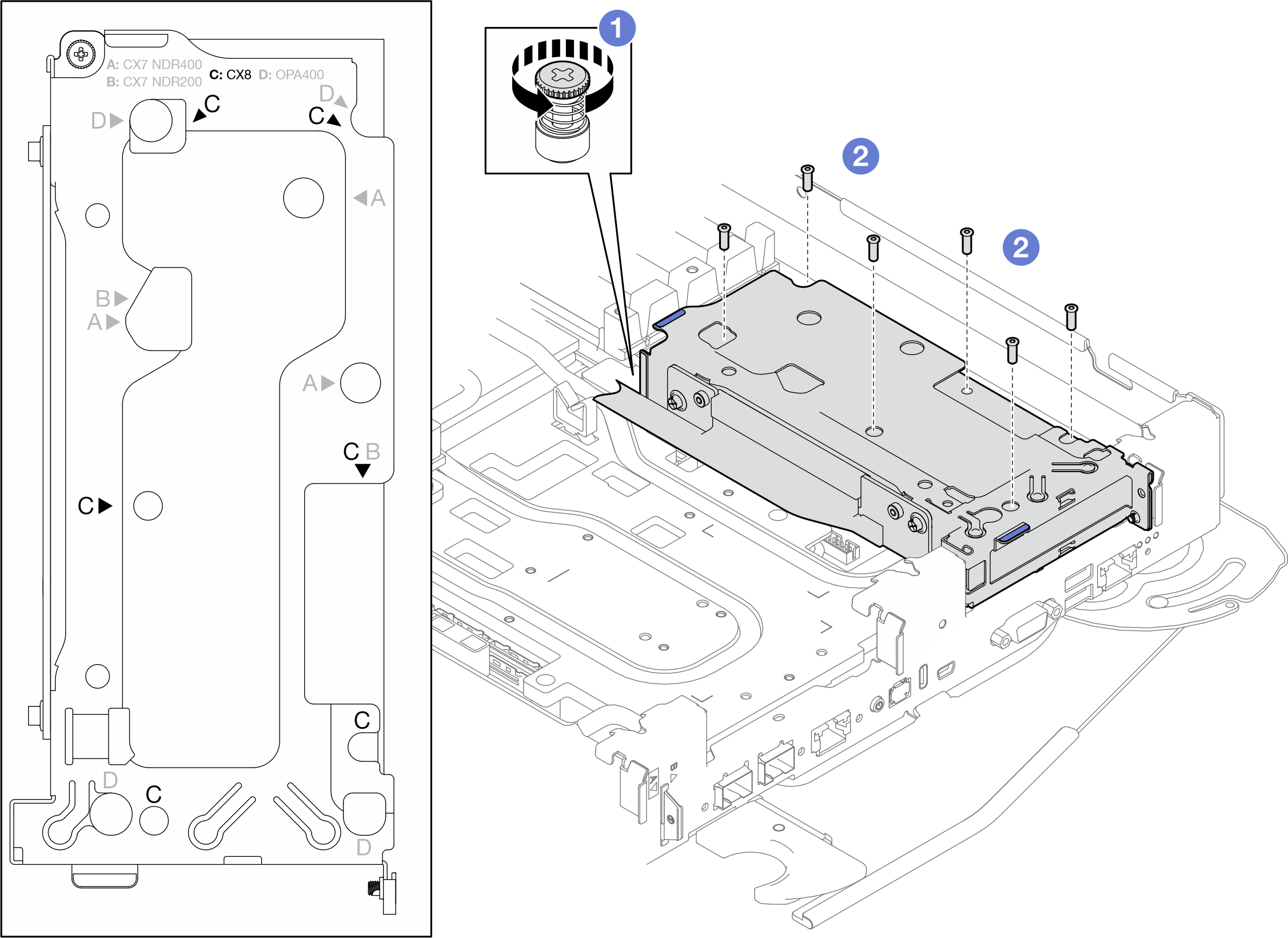 그림 3. 라이저 케이지의 C로 표시된 나사 구멍
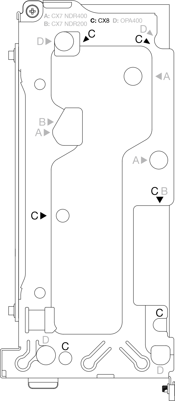
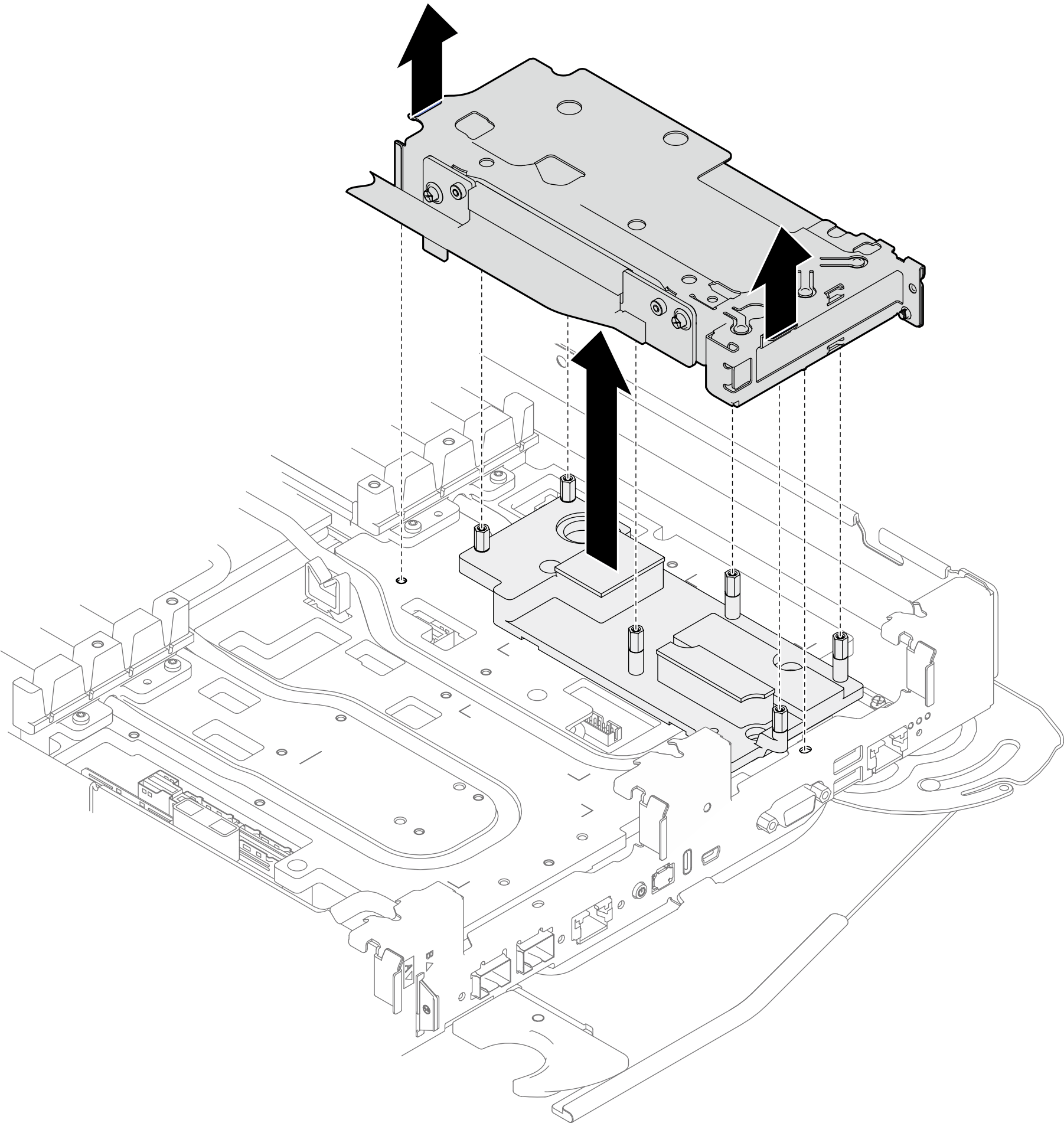
- 라이저 어셈블리의 가장자리를 조심스럽게 잡고 노드에서 라이저 어셈블리를 제거하십시오.그림 4. ConnectX-8 라이저 어셈블리 제거
- 필요한 경우 인터페이스판을 제거하십시오.
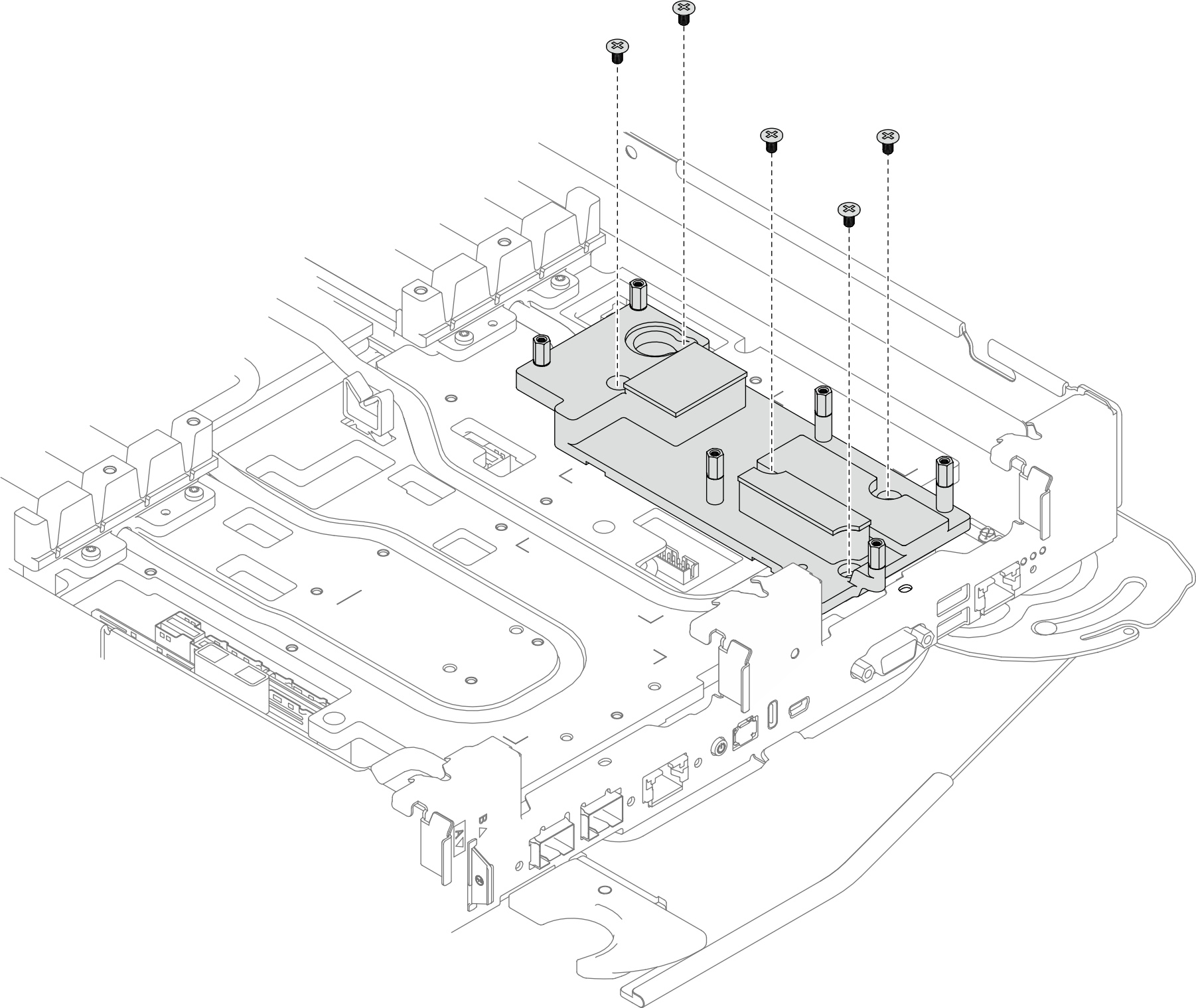
- 인터페이스판에서 PH1 나사 5개를 제거하십시오.그림 5. ConnectX-8 라이저 어셈블리 인터페이스판 제거
- 일자 드라이버로 인터페이스판을 풉니다.
인터페이스판의 하단에는 일자 드라이버 삽입을 위한 구멍이 있습니다(아래 그림에서 검은색 삼각형으로 표시됨). 일자 드라이버를 사용할 수 있는 구멍 하나를 선택하십시오.
구멍에 일자 드라이버를 삽입하십시오. 그런 다음 드라이버를 약간 돌려 워터 루프 냉각판에서 인터페이스판을 분리하십시오.
그림 6. ConnectX-8 라이저 어셈블리 인터페이스판 하단의 개구부 위치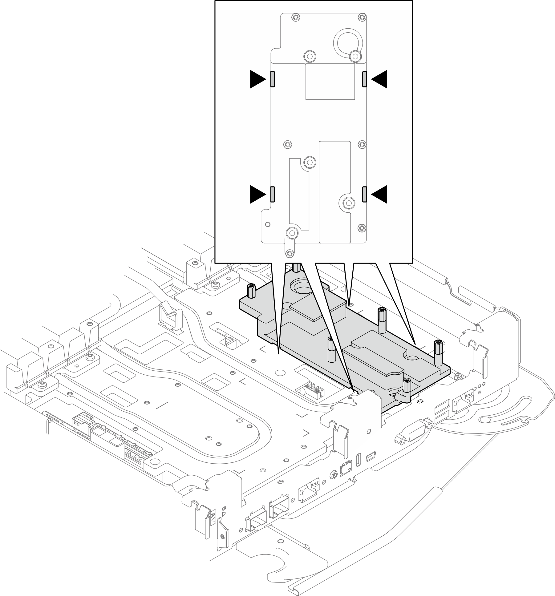 그림 7. 워터 루프 냉각판에서 인터페이스판 분리
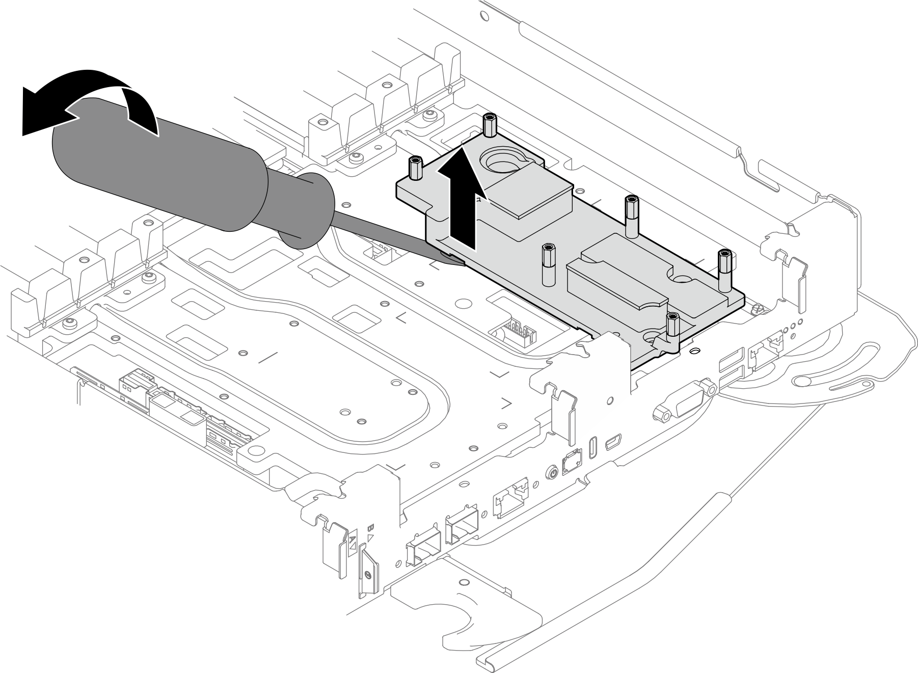
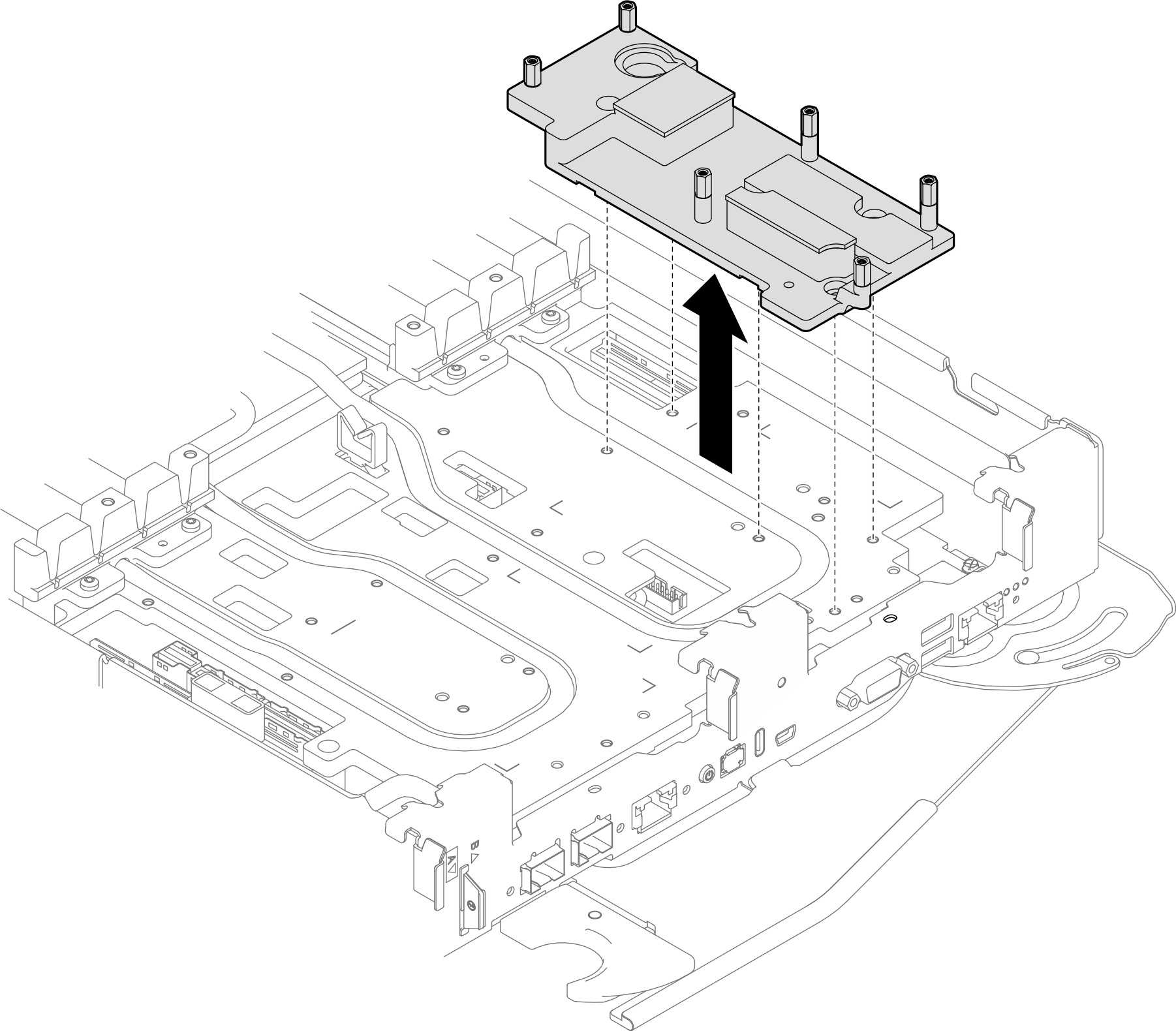
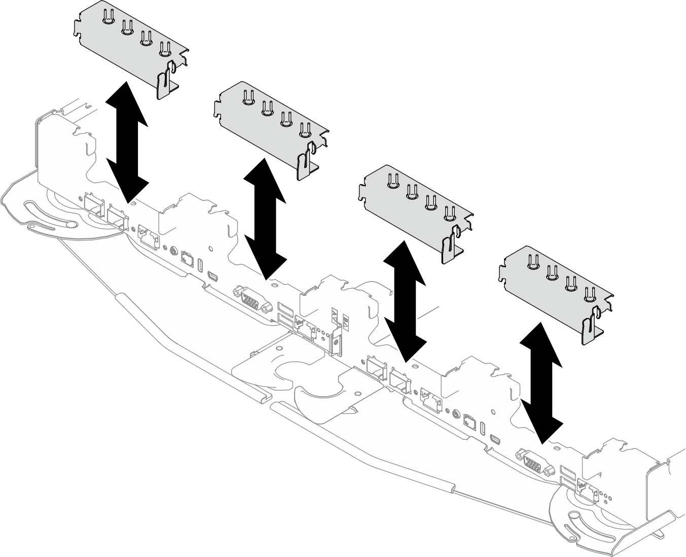
- 트레이에서 인터페이스판을 제거하십시오.그림 8. 인터페이스판 제거
- 인터페이스판에서 PH1 나사 5개를 제거하십시오.
- 라이저 케이지 또는 드라이브 케이지를 설치하지 않을 경우 빈 베젤 필러를 설치하십시오.그림 9. 빈 베젤 필러 설치
완료한 후
구성 요소 또는 옵션 장치를 반환하도록 지시받은 경우 모든 포장 지시사항을 따르고 제공되는 운송용 포장재를 사용하십시오.
피드백 보내기