Install a GPU board assembly(trained technician only)
Use this information to install a GPU board assembly.
About this task
Required tools
Make sure you have the required tools listed below in hand to properly replace the component.
Screws and screwdrivers
Prepare the following screwdrivers to ensure you can install and remove corresponding screws properly.Screw Type Screwdriver Type Hex scerw (GPU node water loop) 6 mm hex screwdriver Torx T10 screw Torx T10 head screwdriver Torx T15 screw Torx T15 head screwdriver M3 screw M3 screwdriver Phillips #1 screw Phillips #1 head screwdriver Phillips #2 screw Phillips #2 head screwdriver
Read Installation Guidelines and Safety inspection checklist to ensure that you work safely.
Turn off the corresponding DWC tray that you are going to perform the task on.
To avoid damaging the water loop, always use the water loop carrier when removing, installing or folding the water loop.
A torque screwdriver is available for request if you do not have one at hand.
- Hold the long sides of the GPU board with two hands while removing the new GPU board from the package box.Figure 1. Removing GPU board assembly from the package box
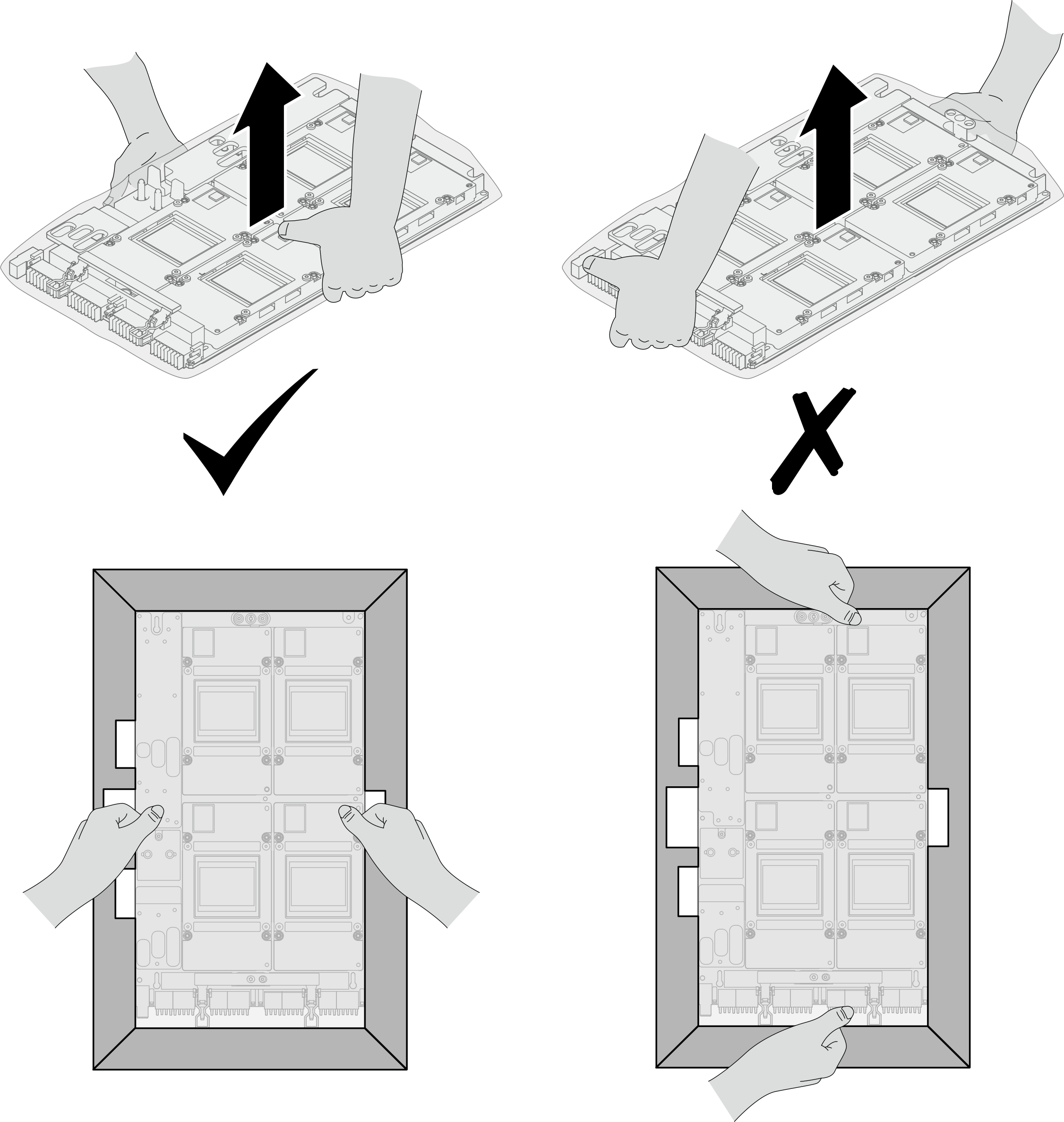
Once the GPU board is removed from the plastic protective bag, hold two handles with both hands to move the GPU board.
Figure 2. Removing GPU board assembly from the package box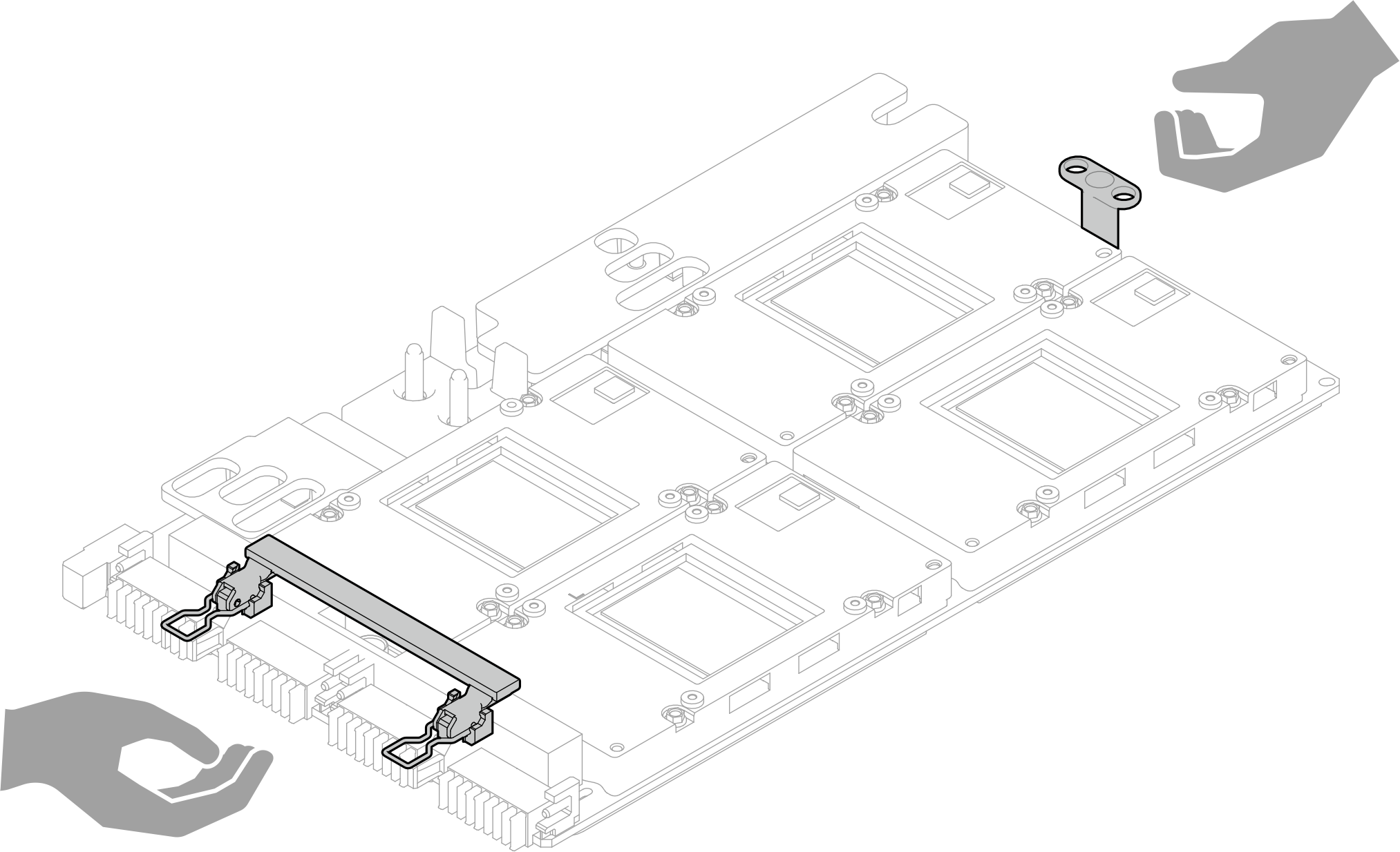
To identify the gap pad/putty pad location and orientation, see Gap pad/Putty pad identification and location.
Before replacing the gap pad/putty pad, gently clean the interface plate or the hardware surface with an alcohol cleaning pad.
Hold the gap pad/putty pad carefully to avoid deformation. Make sure no screw hole or opening is blocked by the gap pad/putty pad material.
Do not use expired putty pad. Check the expiry date on putty pad package. If the putty pads are expired, acquire new ones to properly replace them.
Go to Drivers and Software download website for ThinkSystem SD650-N V3 to see the latest firmware and driver updates for your server.
Go to Update the firmware for more information on firmware updating tools.
- A video of this procedure is available at YouTube.
Procedure
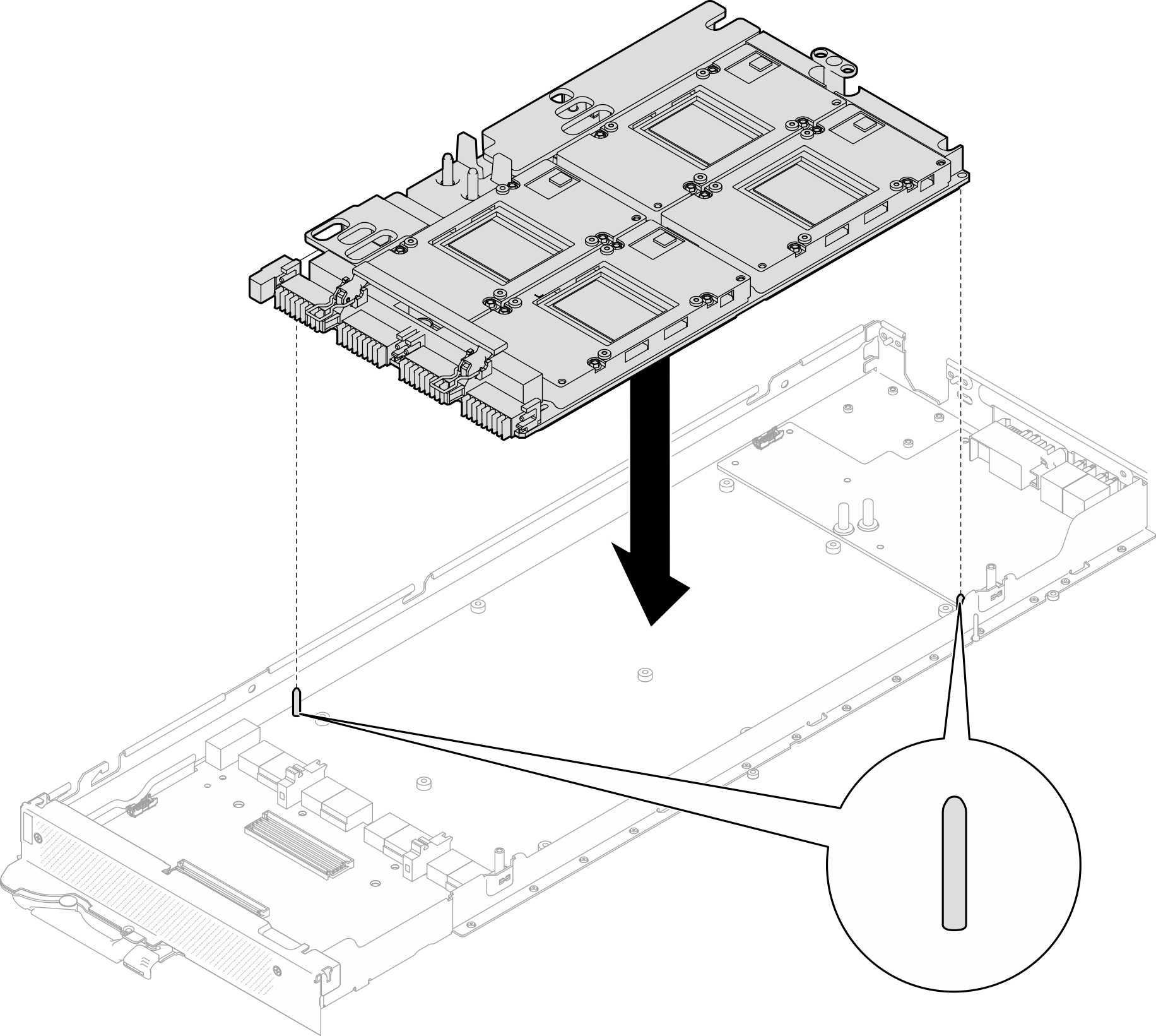
- Align the GPU board assembly with the two guide pins on the tray; then, gently lower down the GPU board assembly to the tray.Figure 3. Installing the GPU board assembly to the node
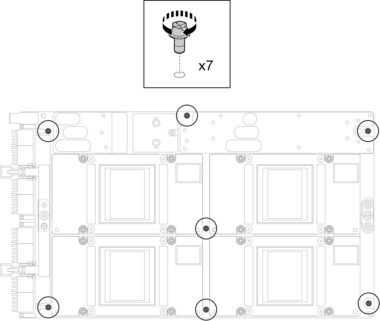
- Install the M3 screws (x7) on the GPU board assembly.NoteFor reference, the torque required for the screws to be fully tightened/removed is 5.0+/- 0.5 lbf-in, 0.55+/- 0.05 N-M.Figure 4. Installing the M3 screws on the GPU board assembly
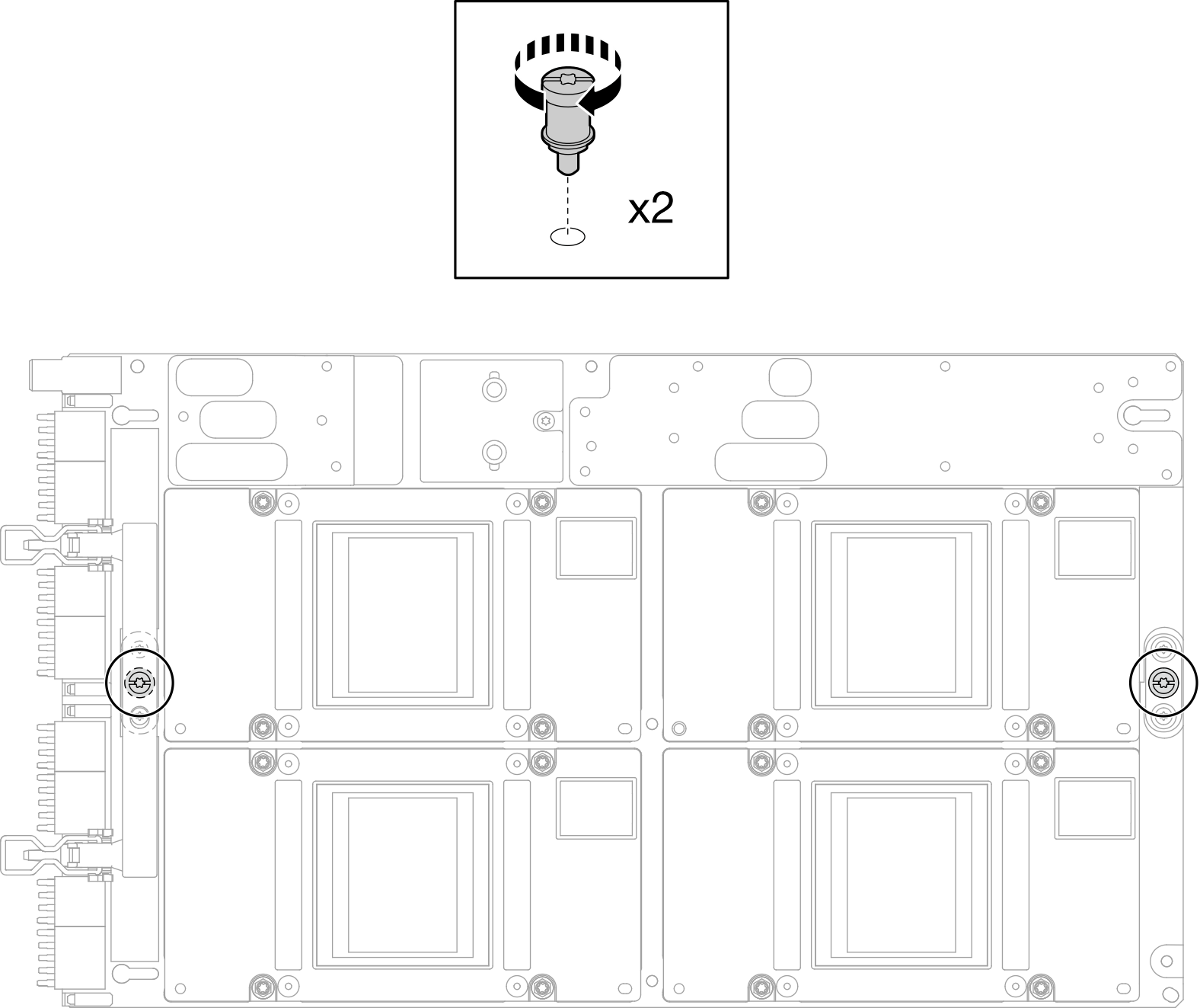
- Install the T15 screws (x2) on the GPU board assembly.NoteFor reference, the torque required for the screws to be fully tightened/removed is 0.6 N-m, 5.3 in-lbf, torque tolerance is +/- 4%.Figure 5. Installing the T15 screws on the GPU board assembly
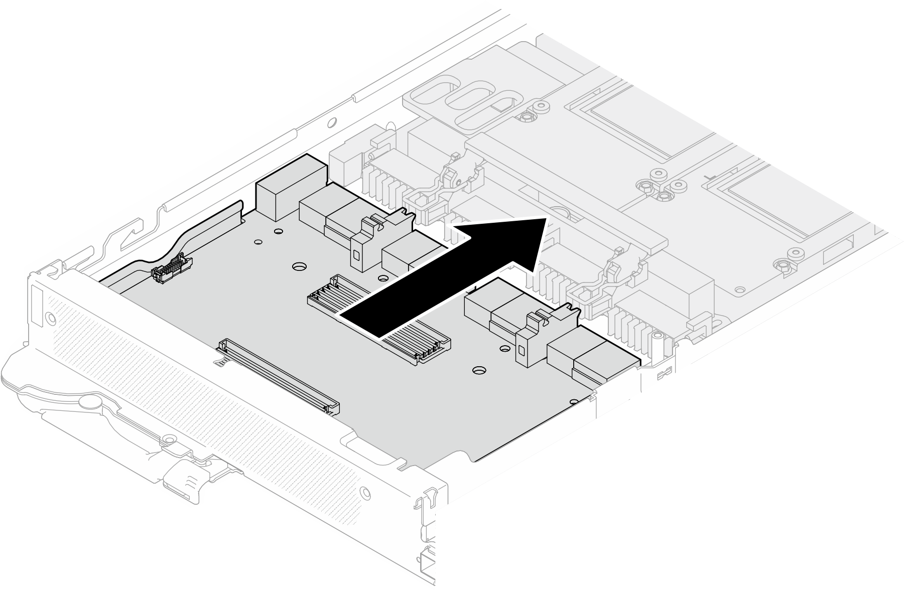
- Push the carrier board to connect it to the GPU board.Figure 6. Connecting the carrier board to the GPU board.
- Secure the carrier board to the GPU board.
 Insert the GPU board retention clips into the slots on the carrier board.
 Rotate the GPU board handle toward the GPU board, and press it down to lock the carrier board in place.
Figure 7. Securing the carrier board to the GPU board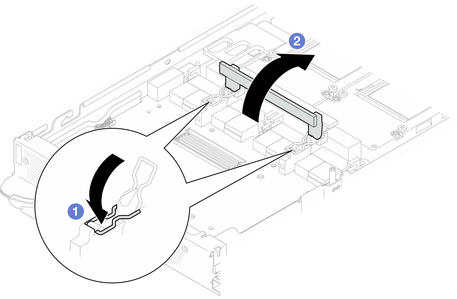
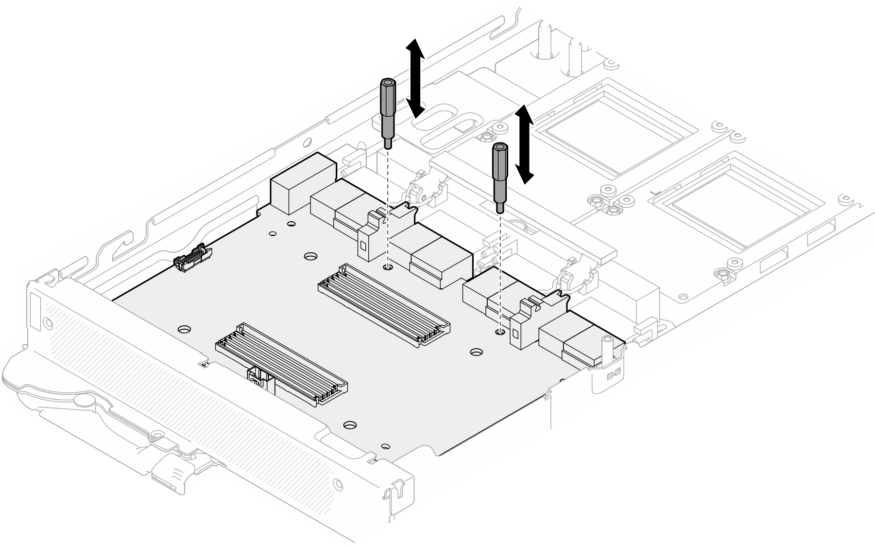
- Install the two standoffs to the carrier board.Figure 8. Installing carrier board standoffs
Install the network board. See Install the network board (trained technician only).
Install the MCIO cables. Follow the guidance and routing information in Internal cable routing.
Install the bus bar. See Install the bus bar.
Install the cross braces. See Install the cross braces.
Install the tray cover. See Install the tray cover.
Install the tray into the enclosure. See Install a DWC tray in the enclosure.
- Connect all required external cables to the solution.NoteUse extra force to connect QSFP cables to the solution.
Check the power LED on each node to make sure it changes from fast blink to slow blink to indicate all nodes are ready to be powered on.