Remove a GPU board assembly (trained technician only)
Use this information to remove a GPU board assembly.
About this task
Required tools
Make sure you have the required tools listed below in hand to properly replace the component.
Screws and screwdrivers
Prepare the following screwdrivers to ensure you can install and remove corresponding screws properly.Screw Type Screwdriver Type Hex scerw (GPU node water loop) 6 mm hex screwdriver Torx T10 screw Torx T10 head screwdriver Torx T15 screw Torx T15 head screwdriver M3 screw M3 screwdriver Phillips #1 screw Phillips #1 head screwdriver Phillips #2 screw Phillips #2 head screwdriver
Read Installation Guidelines and Safety inspection checklist to ensure that you work safely.
Turn off the corresponding DWC tray that you are going to perform the task on.
Disconnect all external cables from the enclosure.
Use extra force to disconnect QSFP cables if they are connected to the solution.
To avoid damaging the water loop, always use the water loop carrier when removing, installing or folding the water loop.
A torque screwdriver is available for request if you do not have one at hand.
- A video of this procedure is available at YouTube.
Procedure
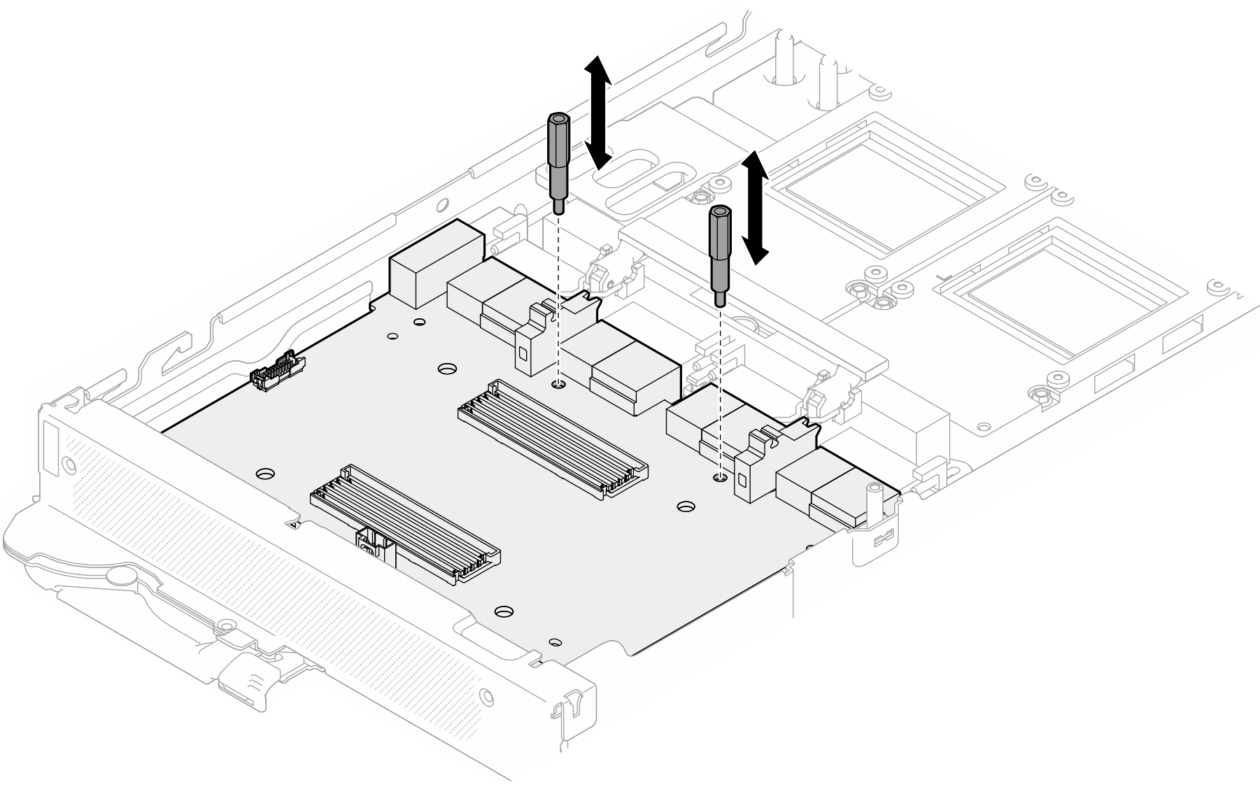
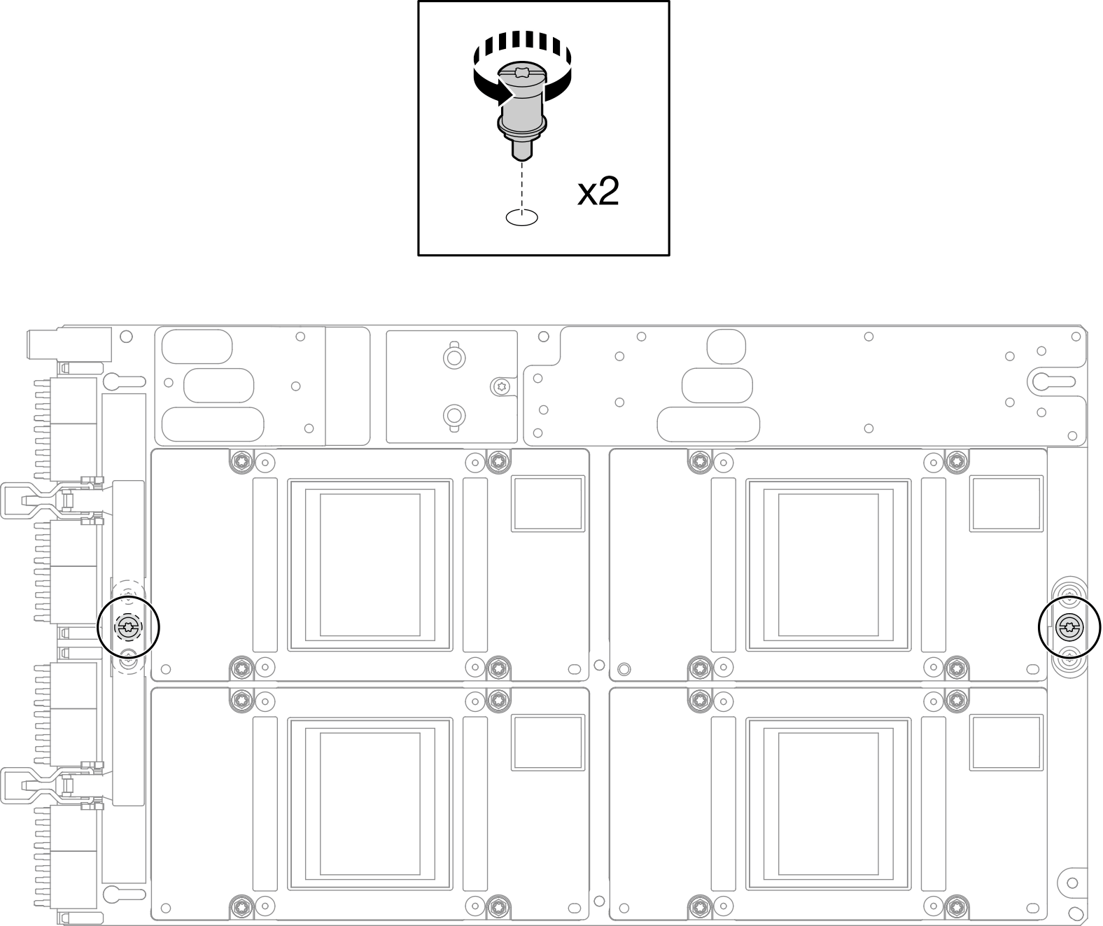
- Remove the two standoffs from the carrier board.Figure 1. Carrier board standoffs removal
- Release the carrier board from the GPU board.
 Rotate the GPU board handle towards the carrier board.
 Release the GPU board retention clips and rotate them towards the GPU board.
Figure 2. Releasing the carrier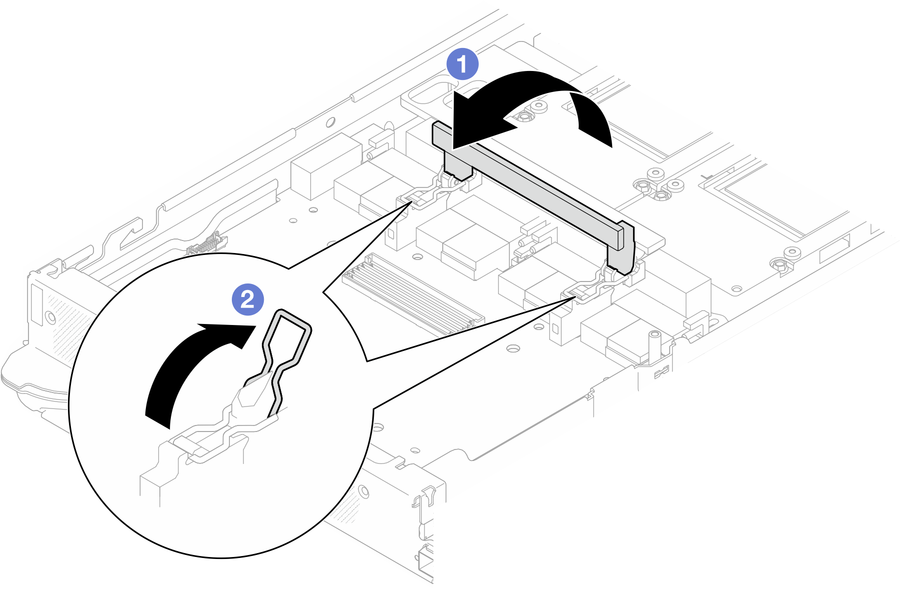
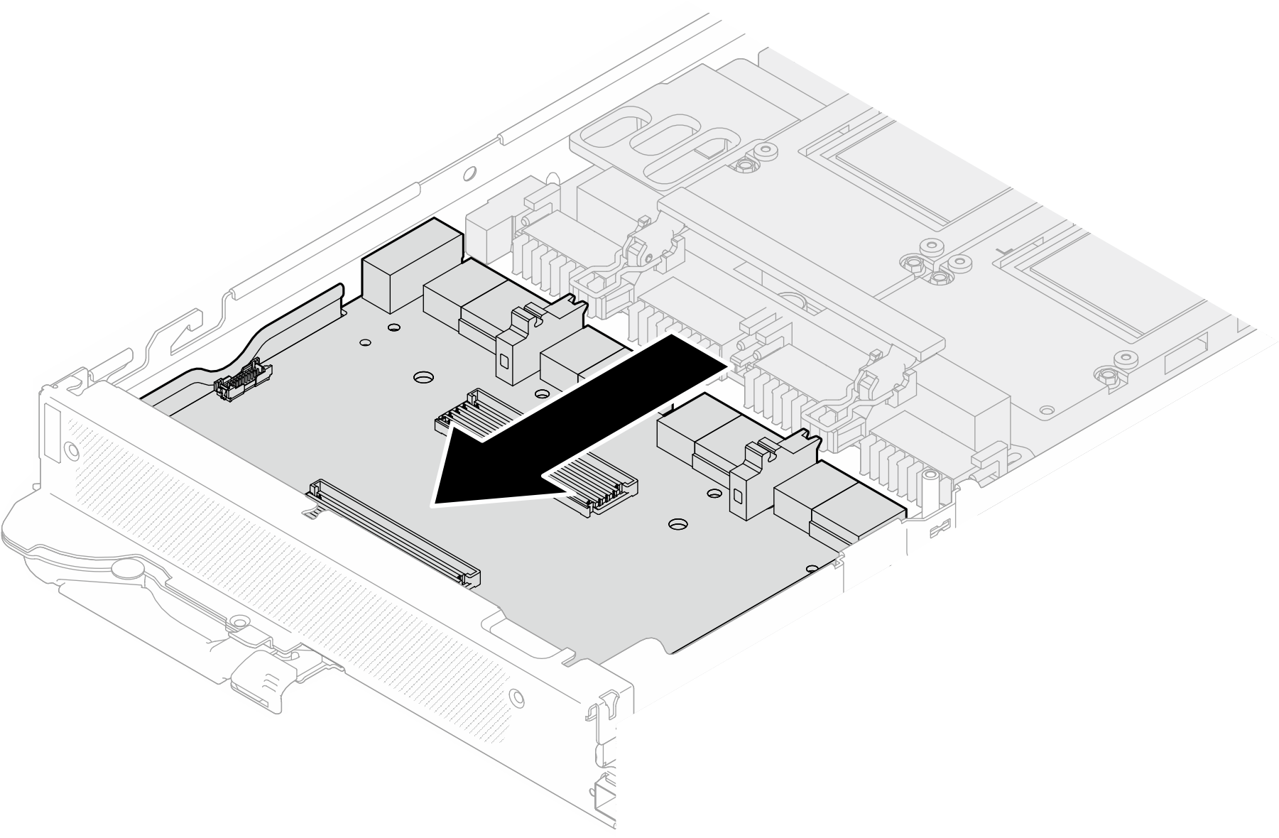
- Disconnect the carrier board from the GPU board.Figure 3. Disconnecting the carrier board from the GPU board
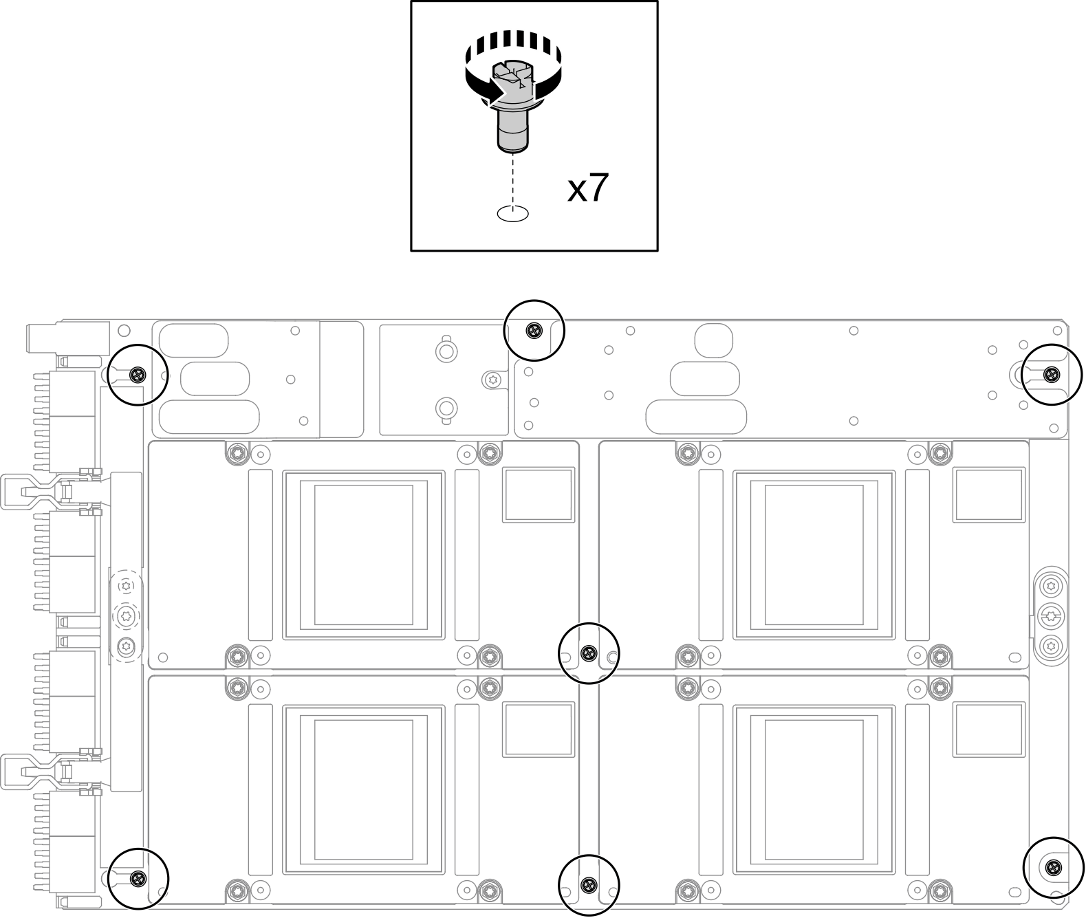
- Remove M3 screws (x7) from the GPU board assembly.NoteFor reference, the torque required for the screws to be fully tightened/removed is 5.0+/- 0.5 lbf-in, 0.55+/- 0.05 N-M.Figure 4. GPU board assembly M3 screws removal
- Remove T15 screws (x2) from the GPU board assembly.NoteFor reference, the torque required for the screws to be fully tightened/removed is 0.6 N-m, 5.3 in-lbf, torque tolerance is +/- 4%.Figure 5. GPU board assembly T15 screws removal
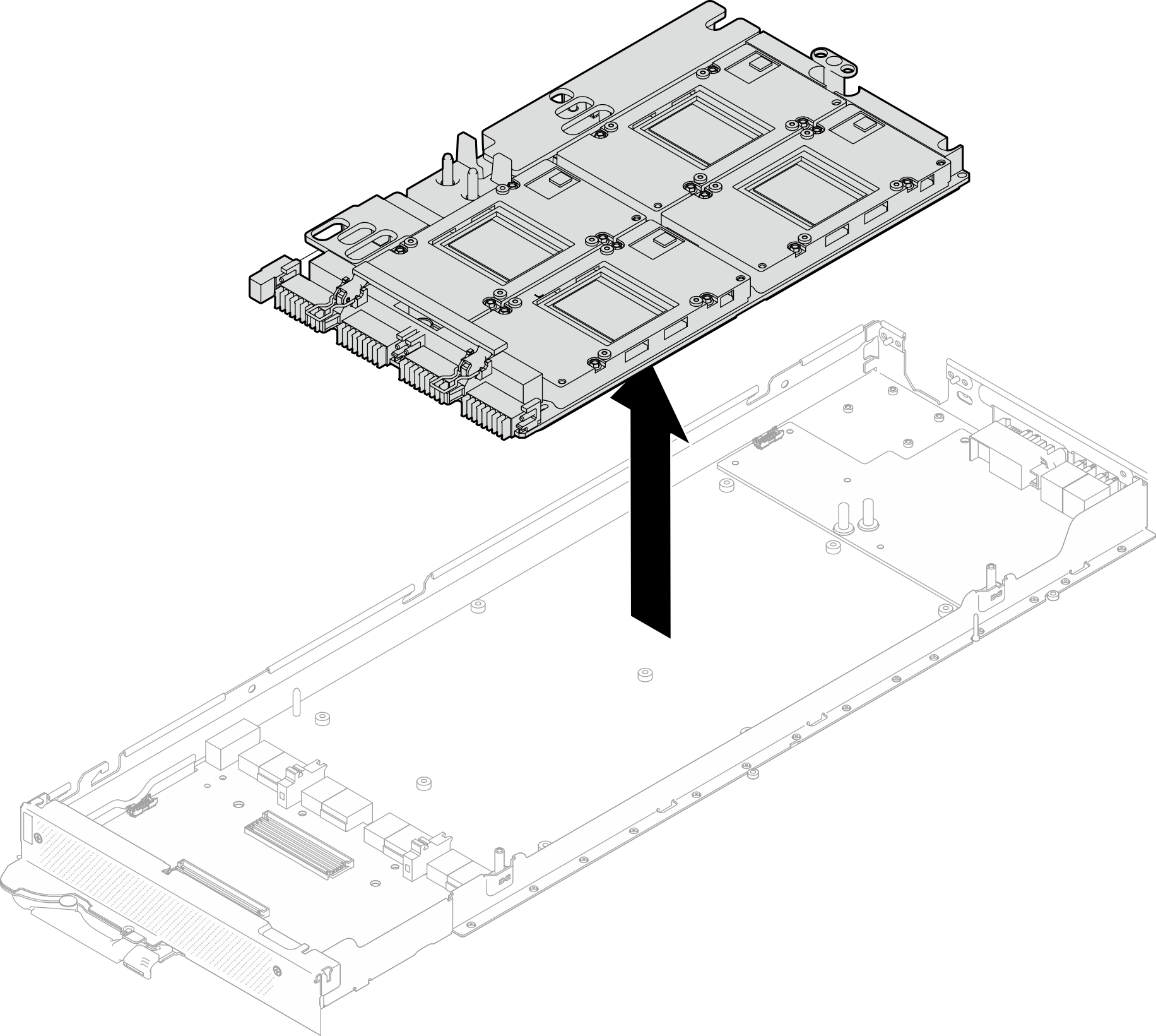
- Remove the GPU board assembly from the node.
If you are instructed to return the component or optional device, follow all packaging instructions, and use any packaging materials for shipping that are supplied to you.