Remove the power distribution board
Use this information to remove the power distribution board.
About this task
Required tools
Make sure you have the required tools listed below in hand to properly replace the component.
Water loop kits
SD650-N V3 Water Loop Gap Pad Kit (The water loop carrier in the Service Kit is reusable, it is recommended to keep it at the facility where the server operates for future replacement needs.)
SD650-N V3 Water Loop Putty Pad Kit
SD650-N V3 OSFP Putty Pad Kit
VR Conduction Plate Parts
Drive gap pad or putty pad kits according to the drives installed in the tray. See their respective replacement procedures for more information.
Screws and screwdrivers
Prepare the following screwdrivers to ensure you can install and remove corresponding screws properly.Screwdriver Type Screw Type Hex screw 4.5 mm hex head screwdriver 3/16" hex head screwdriver hex head screwdriver (power distribution board) Torx T10 head screwdriver Torx T10 screw Torx T30 head screwdriver Torx T30 screw Phillips #1 head screwdriver Phillips #1 screw Phillips #2 head screwdriver Phillips #2 screw
Read Installation Guidelines and Safety inspection checklist to ensure that you work safely.
Turn off the corresponding DWC tray that you are going to perform the task on.
Disconnect all external cables from the enclosure.
Use extra force to disconnect QSFP cables if they are connected to the solution.
To avoid damaging the water loop, always use the water loop carrier when removing, installing or folding the water loop.
- A video of this procedure is available at YouTube.
Procedure
- Remove the two Hex screws from the OSFP module with a 4.5 mm hex head screwdriver.Figure 1. OSFP module conduction plate Hex screws removal
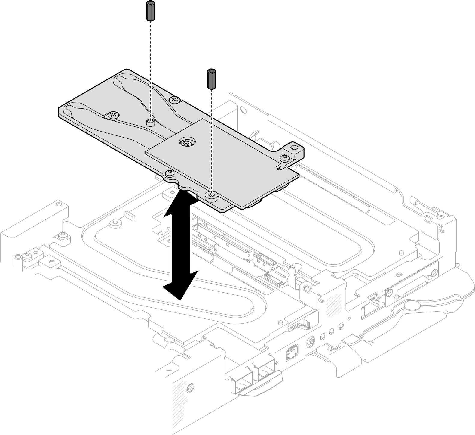
- Remove the OSFP module conduction plate. With alcohol cleaning pads, wipe of any remaining putty pads from the conduction plate.
Screw Type Screwdriver Type 1 M3x5 screw (x3) Phillips #1 head screwdriver 2 M3 screw (x2) T10 screwdriver Figure 2. OSFP module conduction plate removal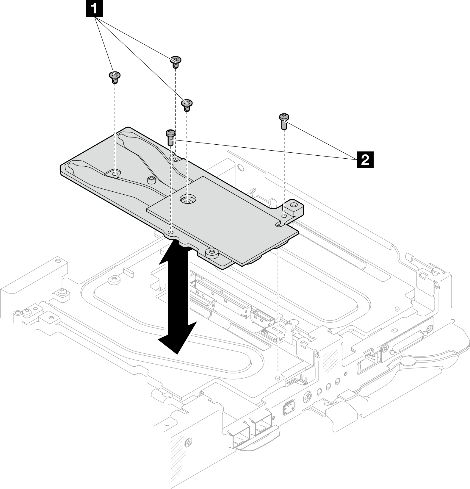
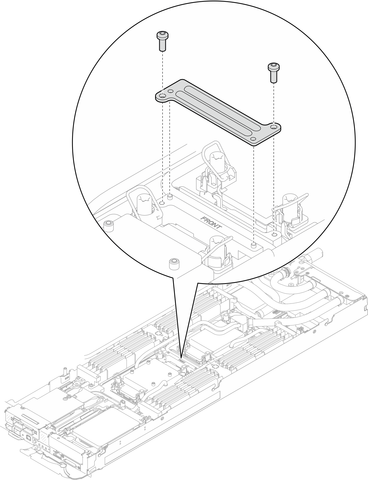
- Remove two Torx T10 screws (per node); then, remove the VR (voltage regulator) clamp plate out of the node.Figure 3. VR clamp plate removal
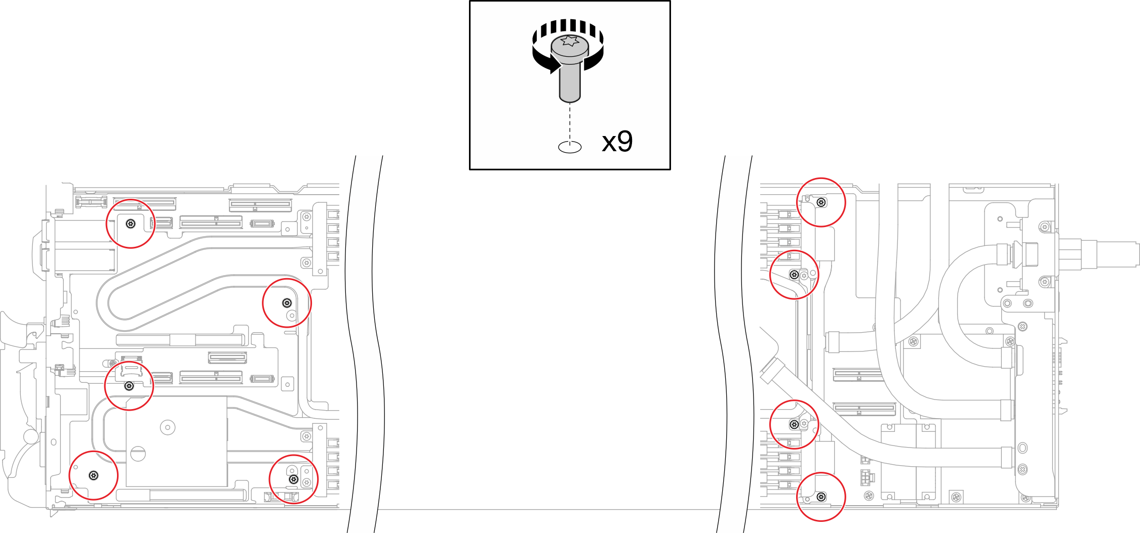
- Remove water loop screws (x9 Torx T10 screws for two nodes) with a torque screwdriver set to the proper torque.NoteFor reference, the torque required for the screws to be fully tightened/removed is 5.0+/- 0.5 lbf-in, 0.55+/- 0.05 N-M.Figure 4. Water loop screw removal
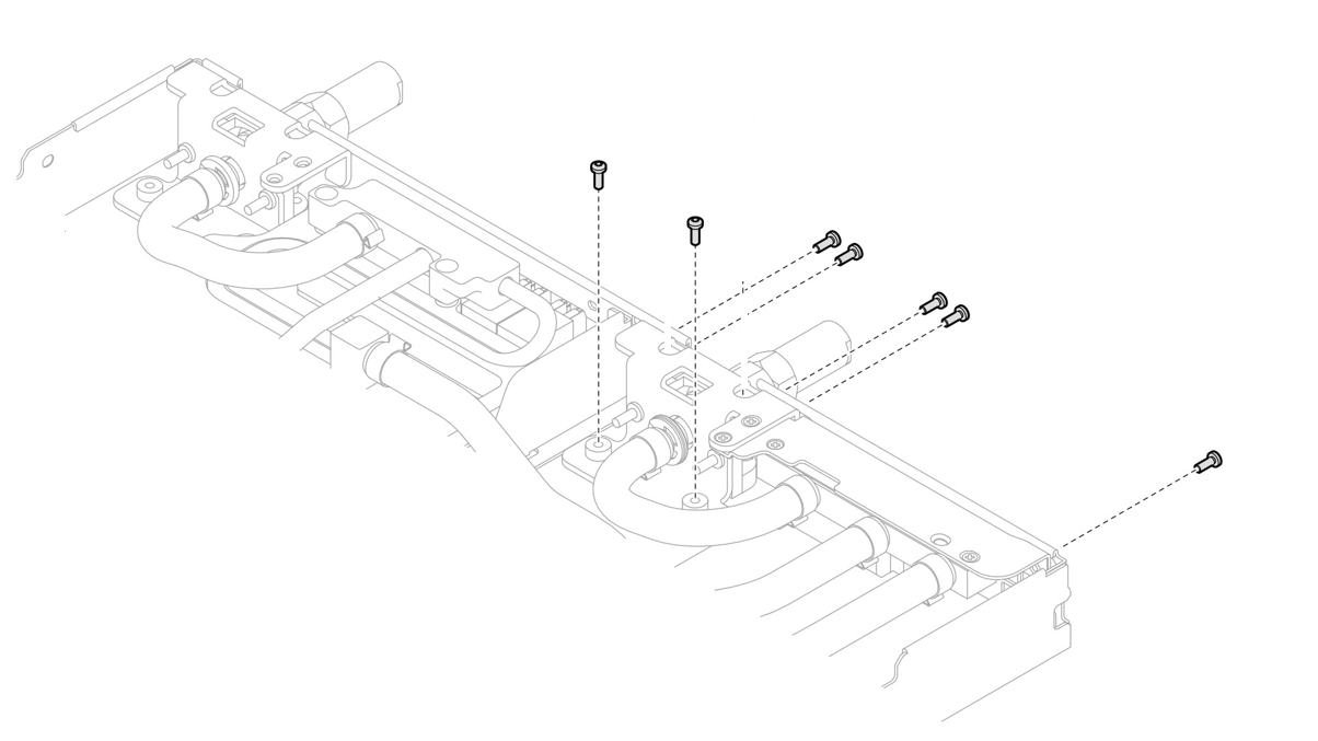
- Remove Torx T10 screws (x7 screws) to loosen the quick connect.NoteFor reference, the torque required for the screws to be fully tightened/removed is 5.0+/- 0.5 lbf-in, 0.55+/- 0.05 N-M.Figure 5. Quick connect screw removal (Compute node)
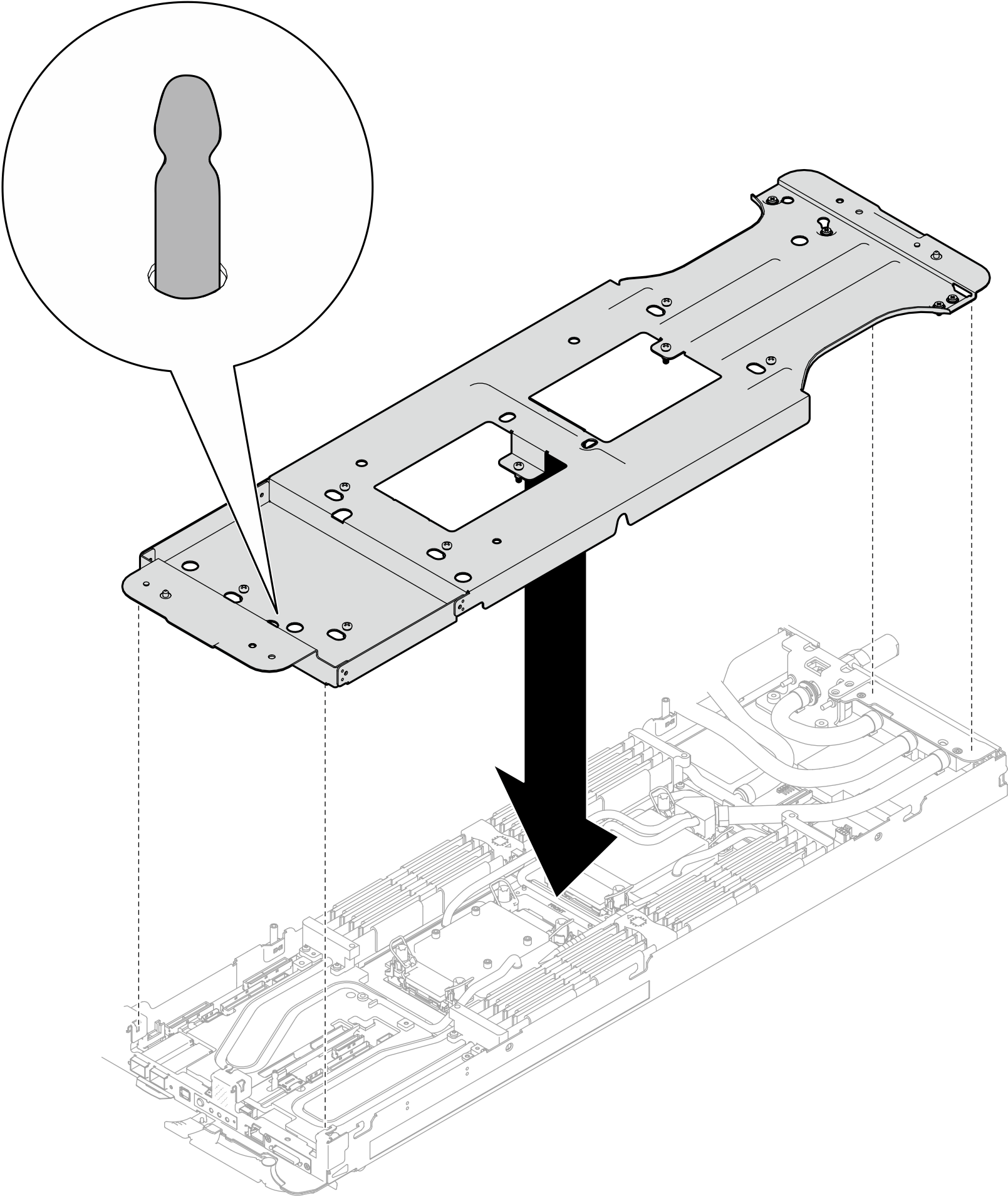
- Orient two water loop carriers with the guide pins; then, gently put the two water loop carriers down and ensure they are seated firmly on the water loop.Figure 6. Water loop carrier installation
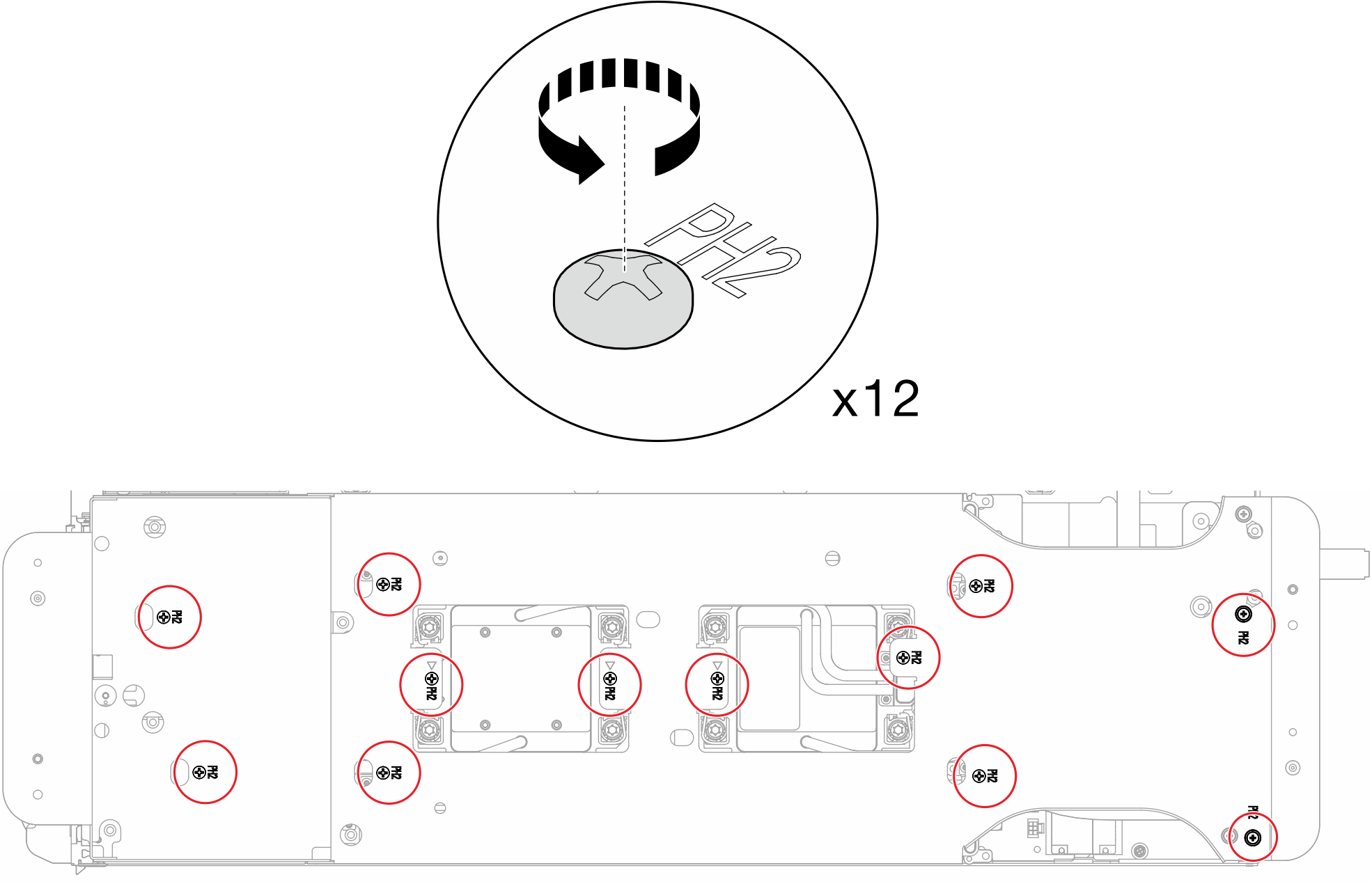
- Tighten water loop carrier screws (x12 Phillips #2 screws).Figure 7. Water loop carrier screws installation
- Loosen processors properly.
 Fully loosen all Torx T30 captive screws (x8 Torx T30 captive screws) on cold plates with a general screwdriver, following the removal sequence shown on the cold plate label.NoteFor reference, the torque required for the screws to be fully tightened/removed is 10+/- 2.0 lbf-in, 1.1+/- 0.2 N-m.AttentionTo prevent damage to components, make sure that you follow the indicated loosening sequence.
 Rotate all anti-tilt wire bails (16x anti-tilt wire bails for two nodes) inwards to the unlocked position.Figure 8. Loosening Torx T30 captive screws
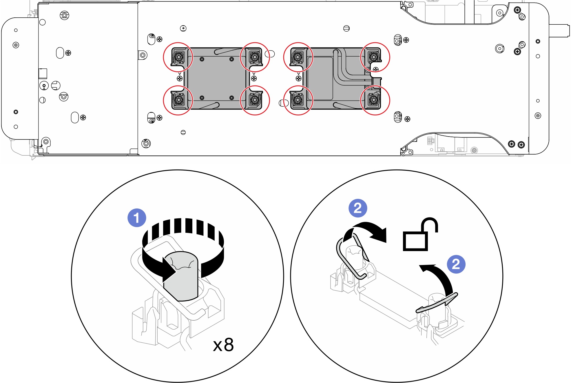
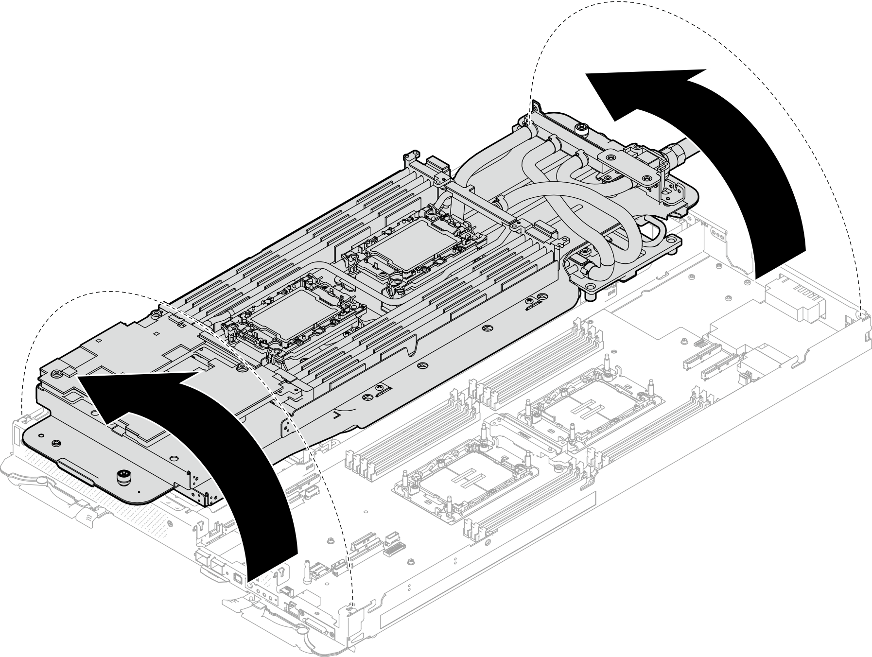
- Carefully rotate the water loop so one half is sitting on top of the other half.Figure 9. Folding the water loop
- Remove the power distribution board.
- Remove the five Phillips #1 screws (per node).
- Gently pull the power distribution board connector to disconnect it from the system board.
 Carefully pull the power distribution board inwards to disengage it from the node.
NoteUse a 3/16" hex head screwdriver to ensure the proper removal and installation.
Figure 10. Power distribution board removal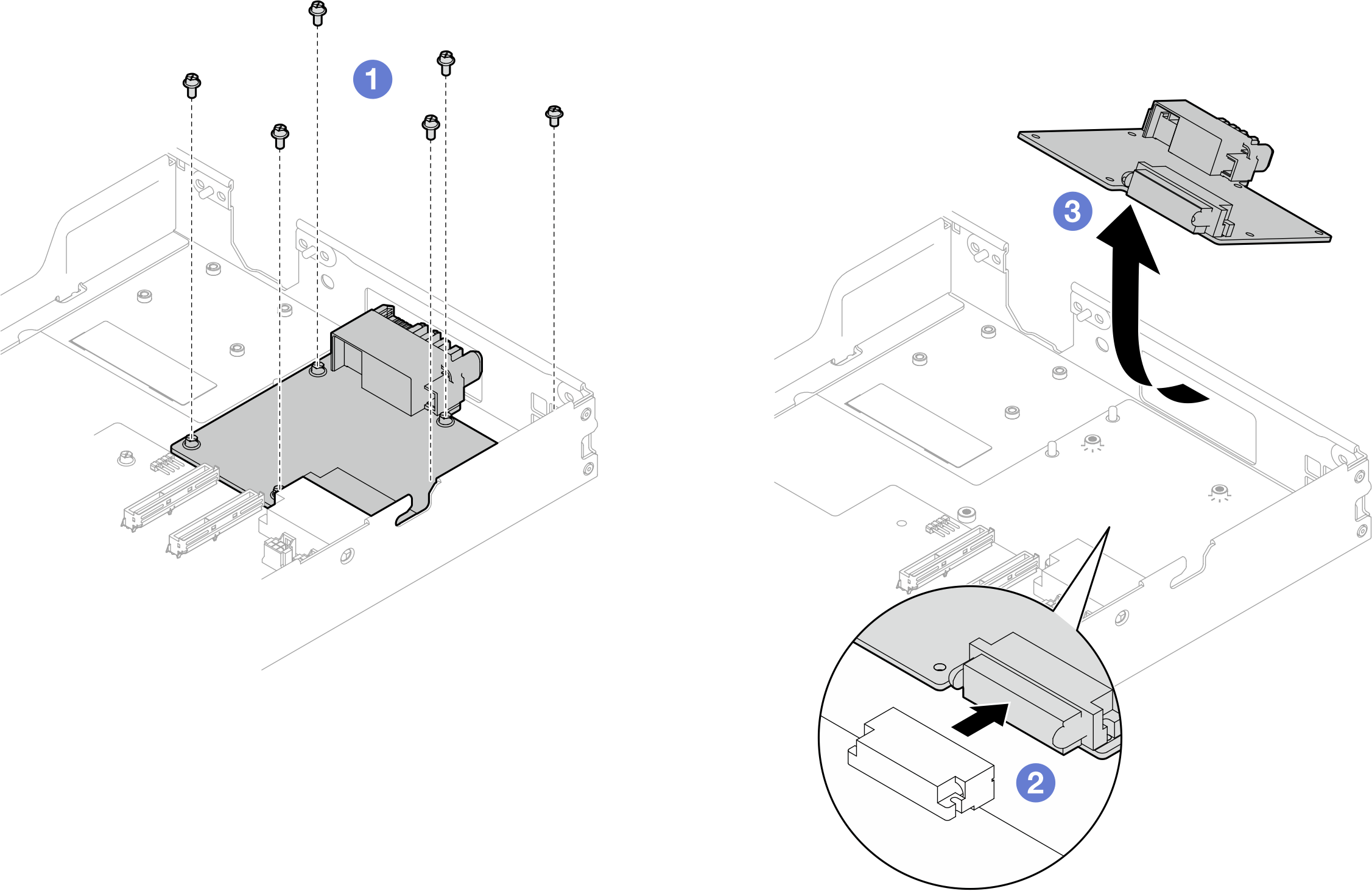
If you are instructed to return the component or optional device, follow all packaging instructions, and use any packaging materials for shipping that are supplied to you.