Install the power distribution board
Use this information to install the power distribution board.
About this task
Required tools
Make sure you have the required tools listed below in hand to properly replace the component.
Water loop kits
SD650-N V3 Water Loop Gap Pad Kit (The water loop carrier in the Service Kit is reusable, it is recommended to keep it at the facility where the server operates for future replacement needs.)
SD650-N V3 Water Loop Putty Pad Kit
SD650-N V3 OSFP Putty Pad Kit
VR Conduction Plate Parts
Drive gap pad or putty pad kits according to the drives installed in the tray. See their respective replacement procedures for more information.
Screws and screwdrivers
Prepare the following screwdrivers to ensure you can install and remove corresponding screws properly.Screwdriver Type Screw Type Hex screw 4.5 mm hex head screwdriver 3/16" hex head screwdriver hex head screwdriver (power distribution board) Torx T10 head screwdriver Torx T10 screw Torx T30 head screwdriver Torx T30 screw Phillips #1 head screwdriver Phillips #1 screw Phillips #2 head screwdriver Phillips #2 screw
To identify the gap pad/putty pad location and orientation, see Gap pad/Putty pad identification and location.
Before replacing the gap pad/putty pad, gently clean the interface plate or the hardware surface with an alcohol cleaning pad.
Hold the gap pad/putty pad carefully to avoid deformation. Make sure no screw hole or opening is blocked by the gap pad/putty pad material.
Do not use expired putty pad. Check the expiry date on putty pad package. If the putty pads are expired, acquire new ones to properly replace them.
Read Installation Guidelines and Safety inspection checklist to ensure that you work safely.
Go to Drivers and Software download website for ThinkSystem SD650-N V3 to see the latest firmware and driver updates for your server.
Go to Update the firmware for more information on firmware updating tools.
- A video of this procedure is available at YouTube.
Procedure
- Install the power distribution board.
 Tilt the power distribution board and align it with the hole; then, slide it into place.
 Gently push the power distribution board connector to ensure it is connected to the system board.
 Fasten the five Phillips #1 screws.
NoteUse a 3/16" hex head screwdriver to ensure the proper removal and installation.
Figure 1. Power distribution board installation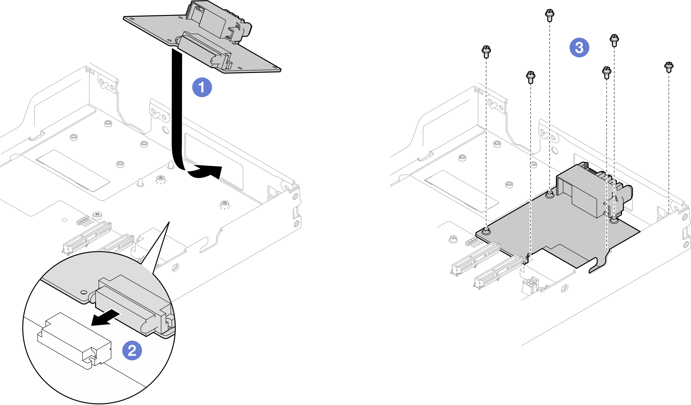
- Check the gap pads on the water loop, if any of them are damaged or detached, replace them with the new ones.Figure 2. Water loop gap pads
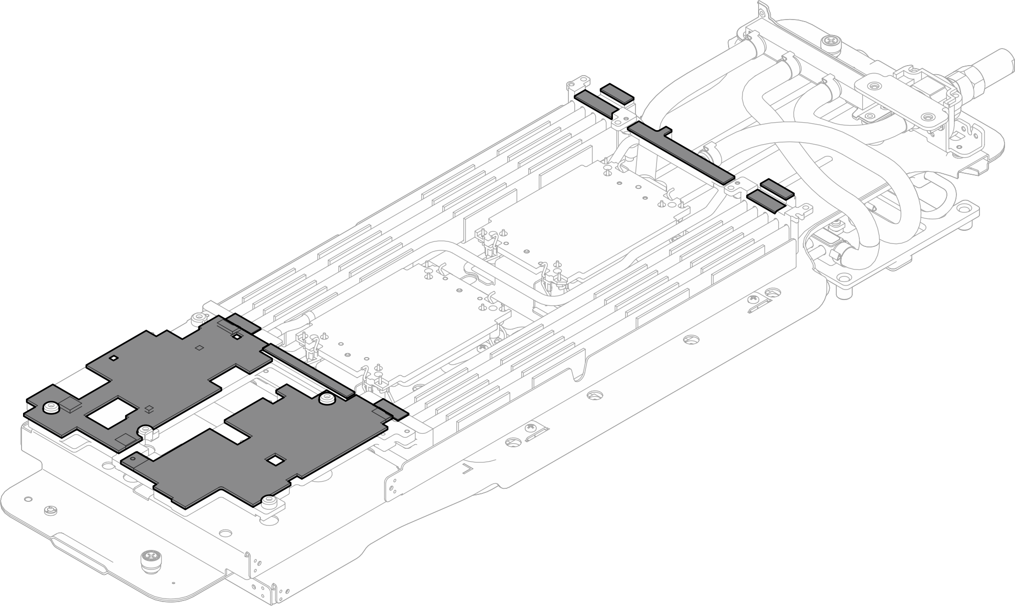
Make sure to follow Gap pad/putty pad replacement guidelines.
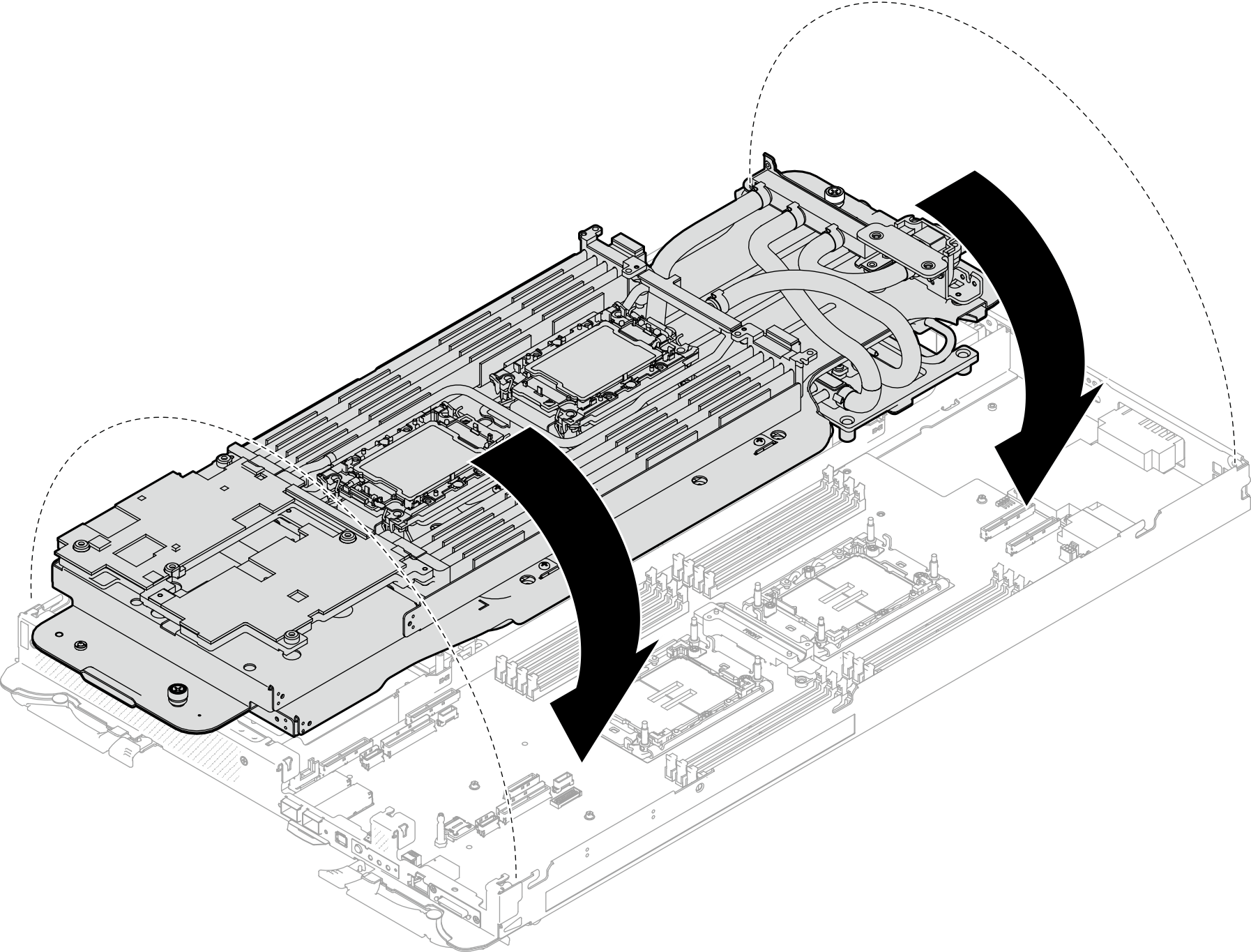
- Carefully rotate the top side of the water loop, position the water loop on the two guide pins near the rear of the node; then, gently put the water loop down and ensure it is firmly seated on the system board.Figure 3. Water loop installation
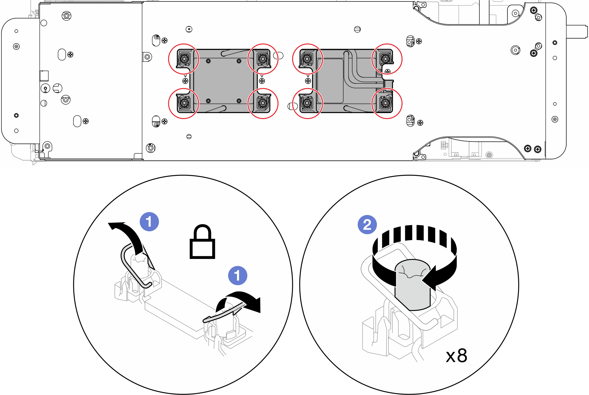
- Ensure the processors are secured properly.
- Rotate 8x anti-tilt wire bails outwards to the locked position.
- Fully tighten 8x Torx T30 captive screws on cold plates with a general screwdriver, following the installation sequence shown on the cold plate label.NoteFor reference, the torque required for the screws to be fully tightened/removed is 10+/- 2.0 lbf-in, 1.1+/- 0.2 N-m.AttentionTo prevent damage to components, make sure that you follow the indicated tightening sequence.Figure 4. Securing Torx T30 captive screws
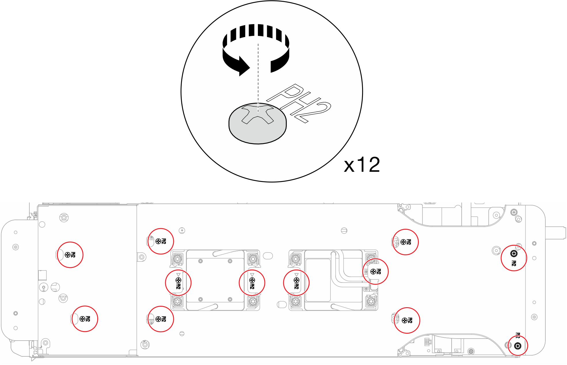
- Loosen water loop carrier screws (x12 Phillips #2 screws for two nodes).Figure 5. Loosening water loop carrier screws
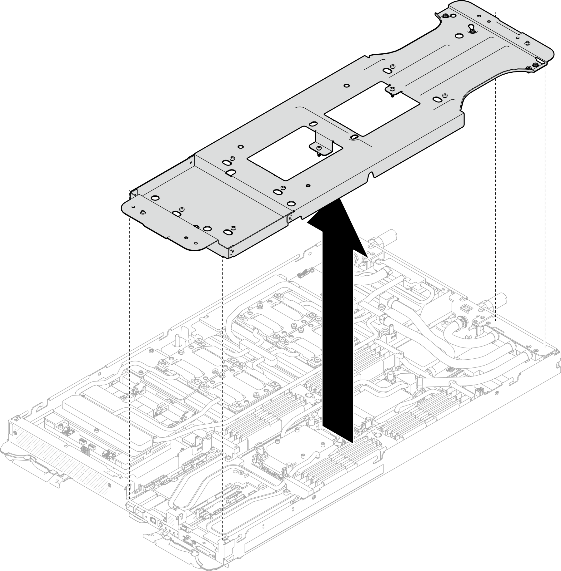
- Carefully lift each water loop carrier up and away from the water loop one at a time.Figure 6. Water loop carrier removal
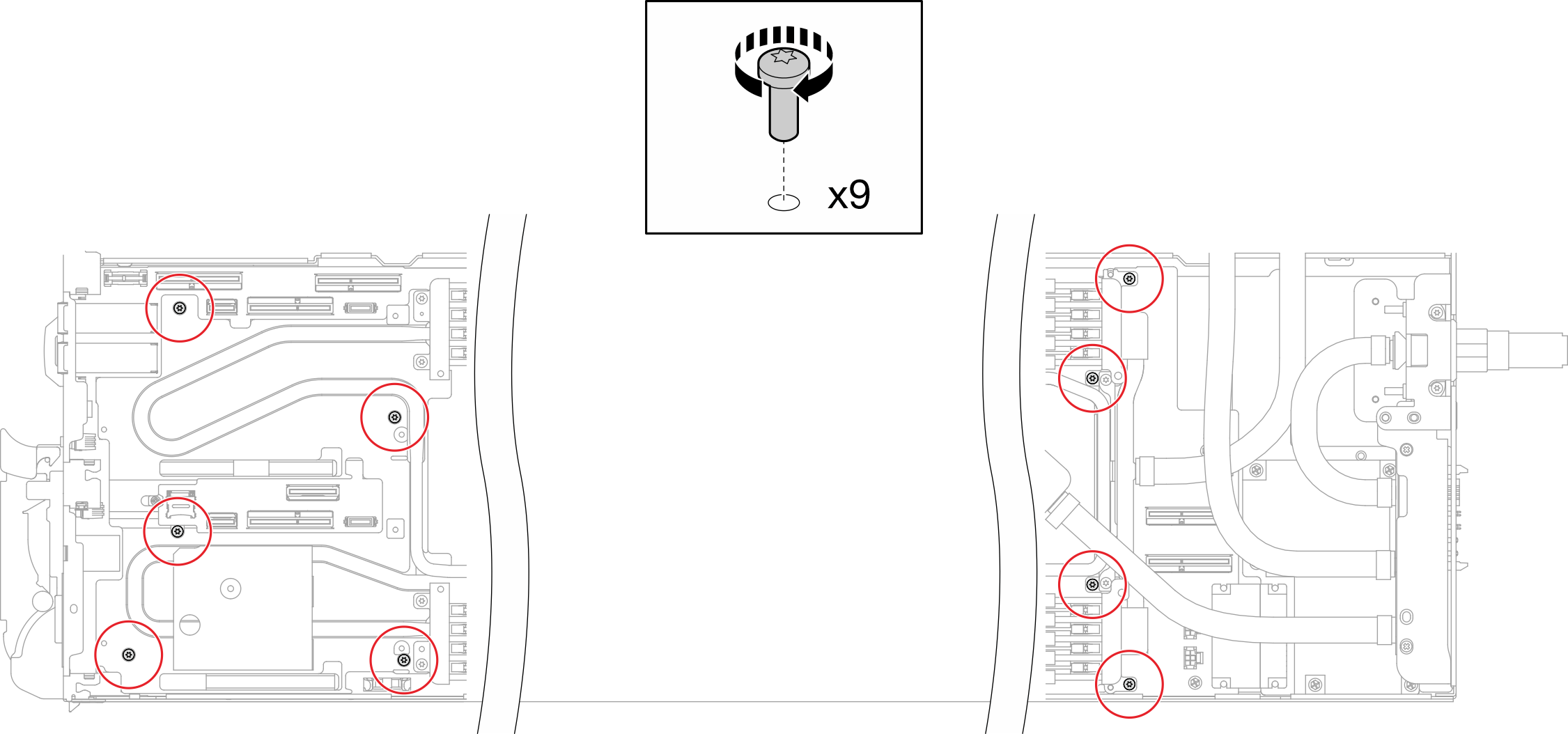
- Install water loop screws (9x Torx T10 screws per node) with a torque screwdriver set to the proper torque.NoteFor reference, the torque required for the screws to be fully tightened/removed is 5.0+/- 0.5 lbf-in, 0.55+/- 0.05 N-M.Figure 7. Water loop screws installation
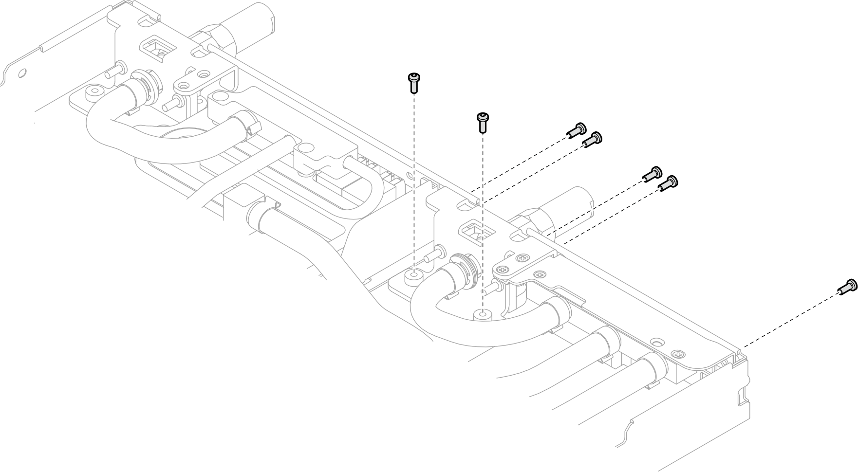
- Install the Torx T10 screws (x7 screws) to secure the quick connect.Figure 8. Quick connect screw installation
- Install two VR clamp plates into the nodes and install Torx T10 screws (4x Torx T10 screws for two nodes).Figure 9. VR clamp plate installation
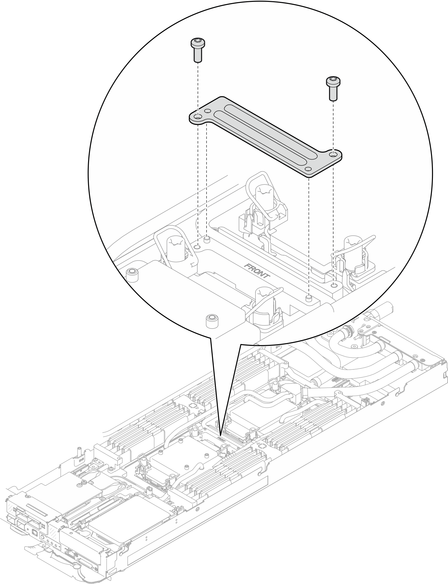
- Replace the putty pads on the top side and the bottom side of the OSFP module conduction plate. Figure 10. OSFP module conduction plate putty pads replacement
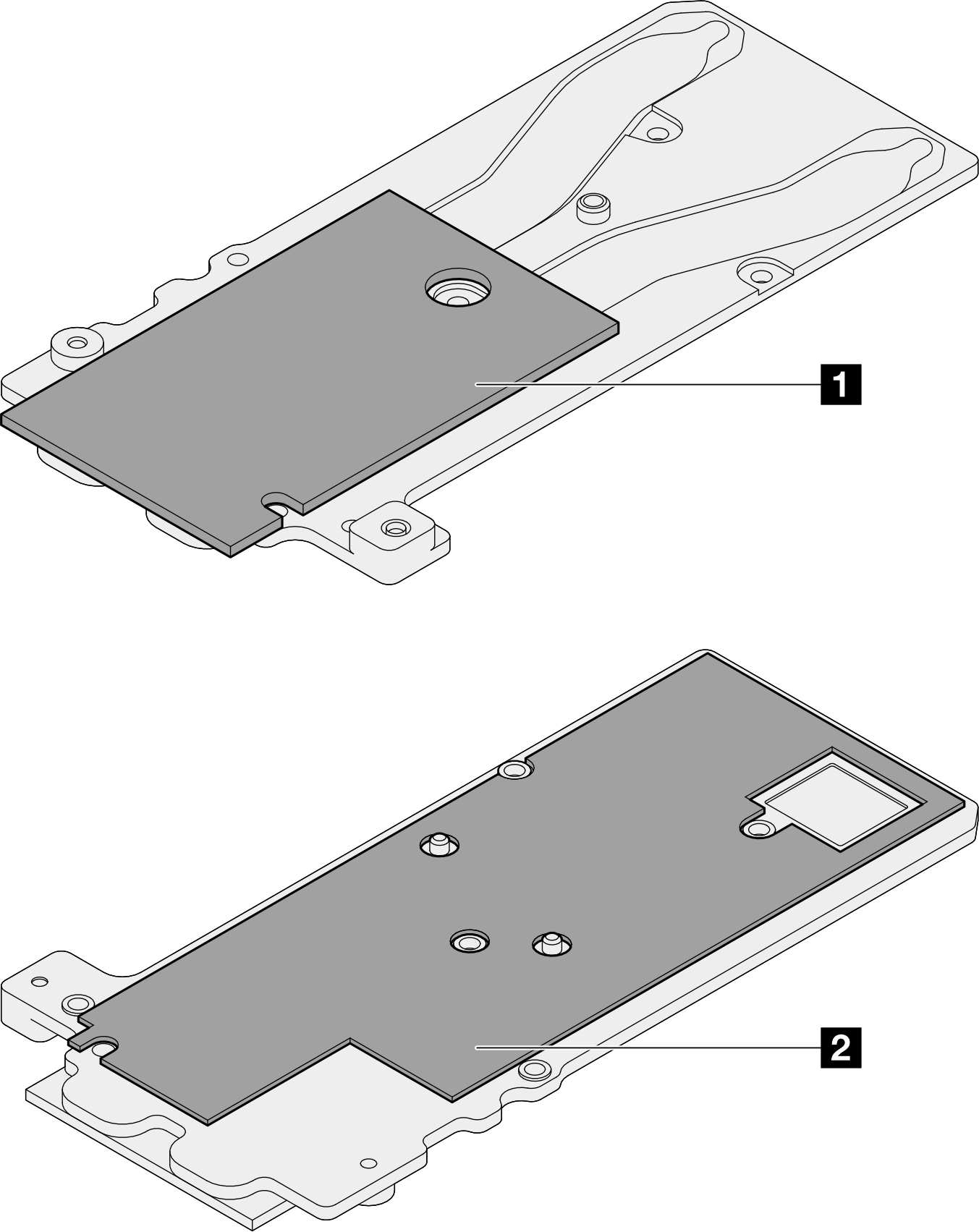
1 Conduction plate top putty pad
2 Conduction plate bottom putty pad
Make sure to follow Gap pad/putty pad replacement guidelines.
- Install the OSFP module conduction plate onto the water loop.
Screw Type Screwdriver Type 1 M3x5 screw (x3) Phillips #1 head screwdriver 2 M3 screw (x2) T10 screwdriver Figure 11. Installing the OSFP module conduction plate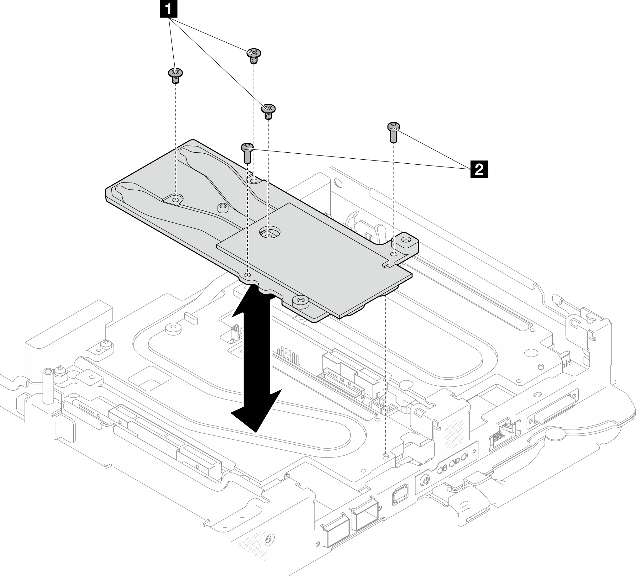
Install the OSFP module. See Install the OSFP module.
Install the drive cage. Depending on system configurations, see Install a drive cage assembly, Install a 7mm NVMe drive cage assembly, or Install the E3.S drive cage assembly.
Install the MCIO cables. Follow the guidance and routing information in Internal cable routing.
Install the bus bar. See Install the bus bar.
Install the M.2 backplane assembly. See Install the M.2 backplane assembly.
Install the memory modules. See Install a memory module.
Install the DIMM comb. See Install a DIMM comb.
Install the cross braces. See Install the cross braces.
Install the tray cover. See Install the tray cover.
Install the tray into the enclosure. See Install a DWC tray in the enclosure.
- Connect all required external cables to the solution.NoteUse extra force to connect QSFP cables to the solution.
Check the power LED on each node to make sure it changes from fast blink to slow blink to indicate all nodes are ready to be powered on.