Remove the OSFP module and network board (trained technician only)
Use this information to remove the OSFP module and network board.
If replacing only the network board, refer to Network board (trained technician only).
About this task
Required tools
Make sure you have the required tools listed below in hand to properly replace the component.
GPU node water loop carrier
(The water loop carrier in the Service Kit is reusable, it is recommended to keep it at the facility where the server operates for future replacement needs.)
SD665-N V3 Water Loop Gap Pad Kit
SD665-N V3 Miscellaneous Parts Kit
SD665-N V3 Water Loop Putty Pad Kit
SD665-N V3 SXM5 PCM Fixture
- SXM5 PCM Kit (for GPU replacement)NoteContact Lenovo service engineer for guidance on selecting PCM type based on inlet water temperature.
SD665-N V3 OSFP Putty Pad Kit
Putty pad cannot be reused. Whenever the water loop is removed, putty pads must be replaced with new ones before reinstalling the water loop.
Screw and screwdrivers
Prepare the following screwdrivers to ensure you can install and remove corresponding screws properly.Prepare the following screwdrivers to ensure you can install and remove corresponding screws properly.Screw Type/Usage Screwdriver Type Hex screw (GPU node water loop) 6 mm hex head screwdriver Releasing OSFP module from conduction plate Flat head screwdriver Torx T10 screw Torx T10 head screwdriver Torx T15 screw Torx T15 head screwdriver Phillips #1 screw Phillips #1 head screwdriver Phillips #2 screw Phillips #2 head screwdriver
Read Installation Guidelines and Safety inspection checklist to ensure that you work safely.
Turn off the corresponding DWC tray that you are going to perform the task on.
Disconnect all external cables from the enclosure.
Use extra force to disconnect QSFP cables if they are connected to the solution.
To avoid damaging the water loop, always use the water loop carrier when removing, installing or folding the water loop.
A torque screwdriver is available for request if you do not have one at hand.
Remove the OSFP module
Procedure
- Disconnect the drive cage cable.Figure 1. Disconnecting drive cable
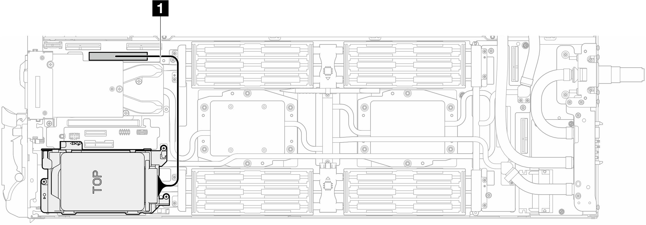 Figure 2. Disconnecting 7mm drive cableFigure 3. Disconnecting E3.S drive cable
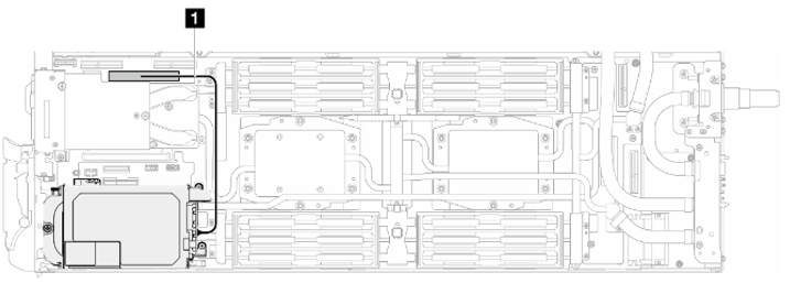
- Disconnect MCIO cables from carrier board.One-processor configuration: disconnect all MCIO cables from the carrier boardFigure 4. One-processor configuration—Disconnecting all MCIO cables
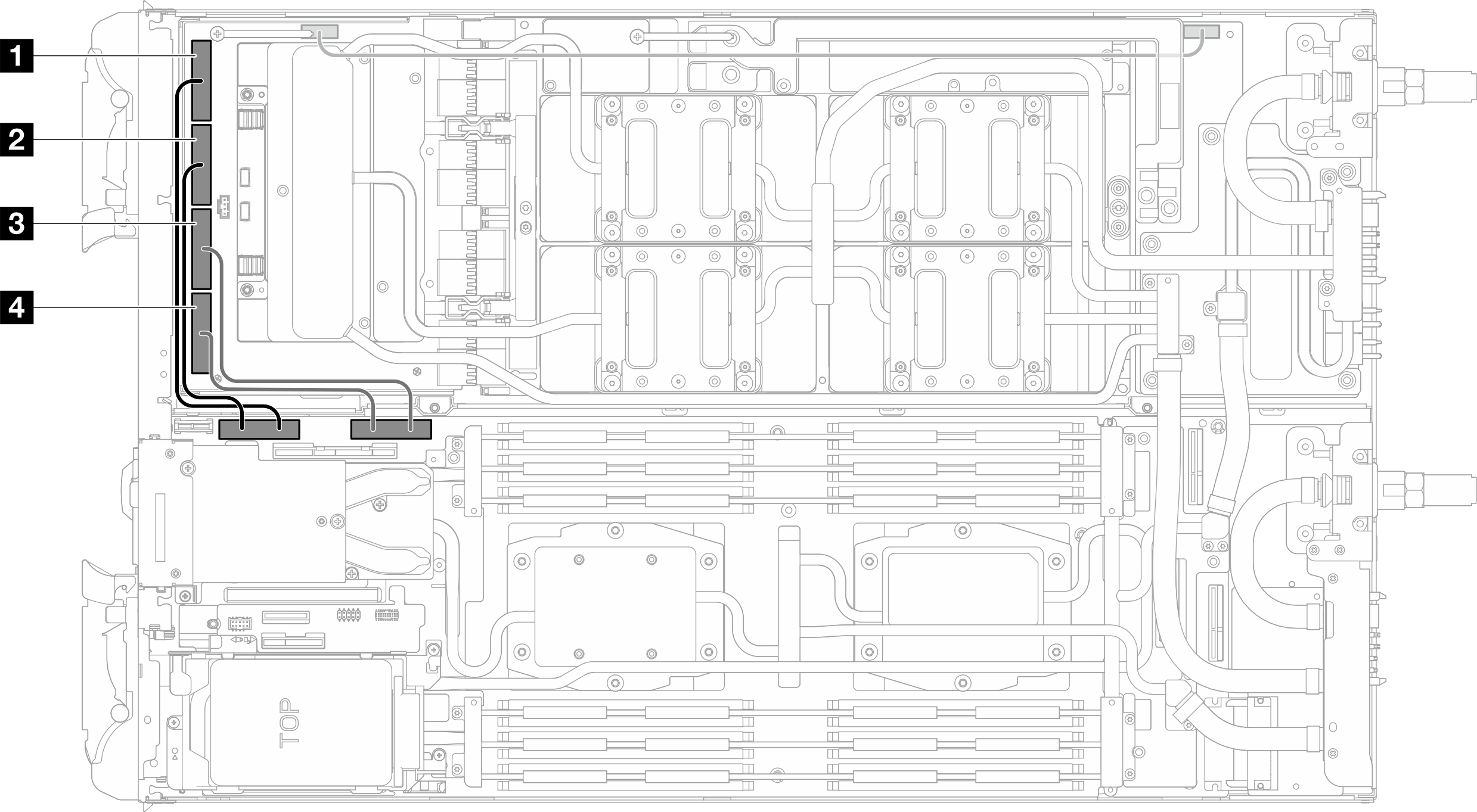
Cable index From (carrier board in GPU node) To (system board in compute node) 1 MCIO 1 cable PCIe 4 2 MCIO 2 cable 3 MCIO 3 cable PCIe 3 4 MCIO 4 cable Two-processors configuration: disconnect MCIO 2, MCIO 3, and MCIO 4cables from the carrier boardFigure 5. Two-processors configuration–Disconnecting MCIO 2, MCIO 3, and MCIO 4 cables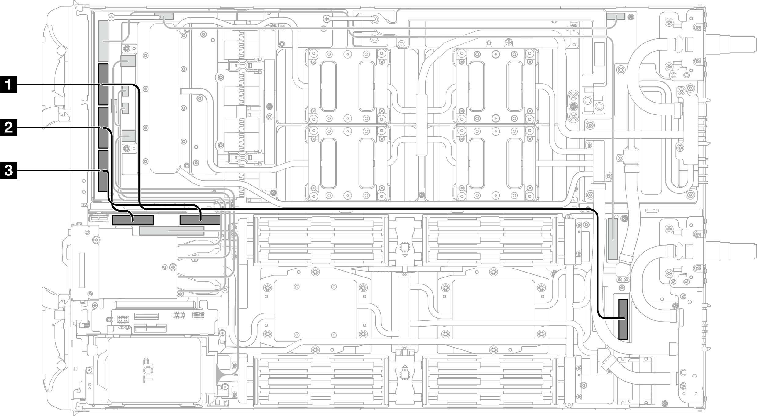
Cable index From (carrier board in GPU node) To (system board in compute node) 1 MCIO 2 cable PCIe 5 2 MCIO 3 cable PCIe 4 3 MCIO 4 cable PCIe 3 - Disconnect the OSFP module cables from the network board on the GPU node.Note
Two cables are labeled with a 45 degree label. Be careful when removing these two cables as they are fragile and can often break when removed. The cable should be removed at a 45-degree angle with as little force as possible.
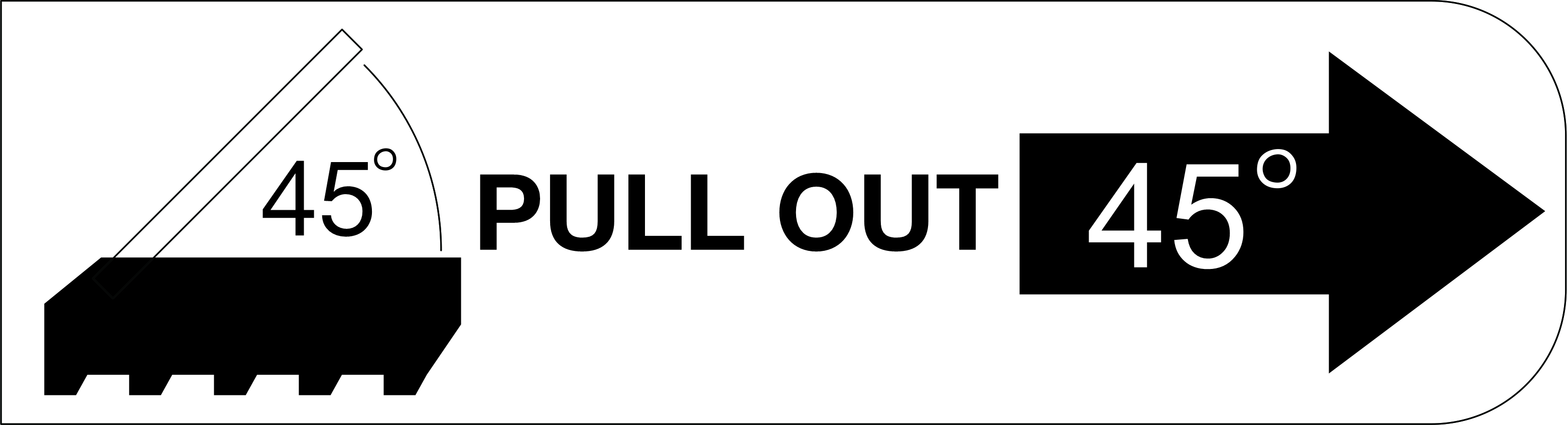
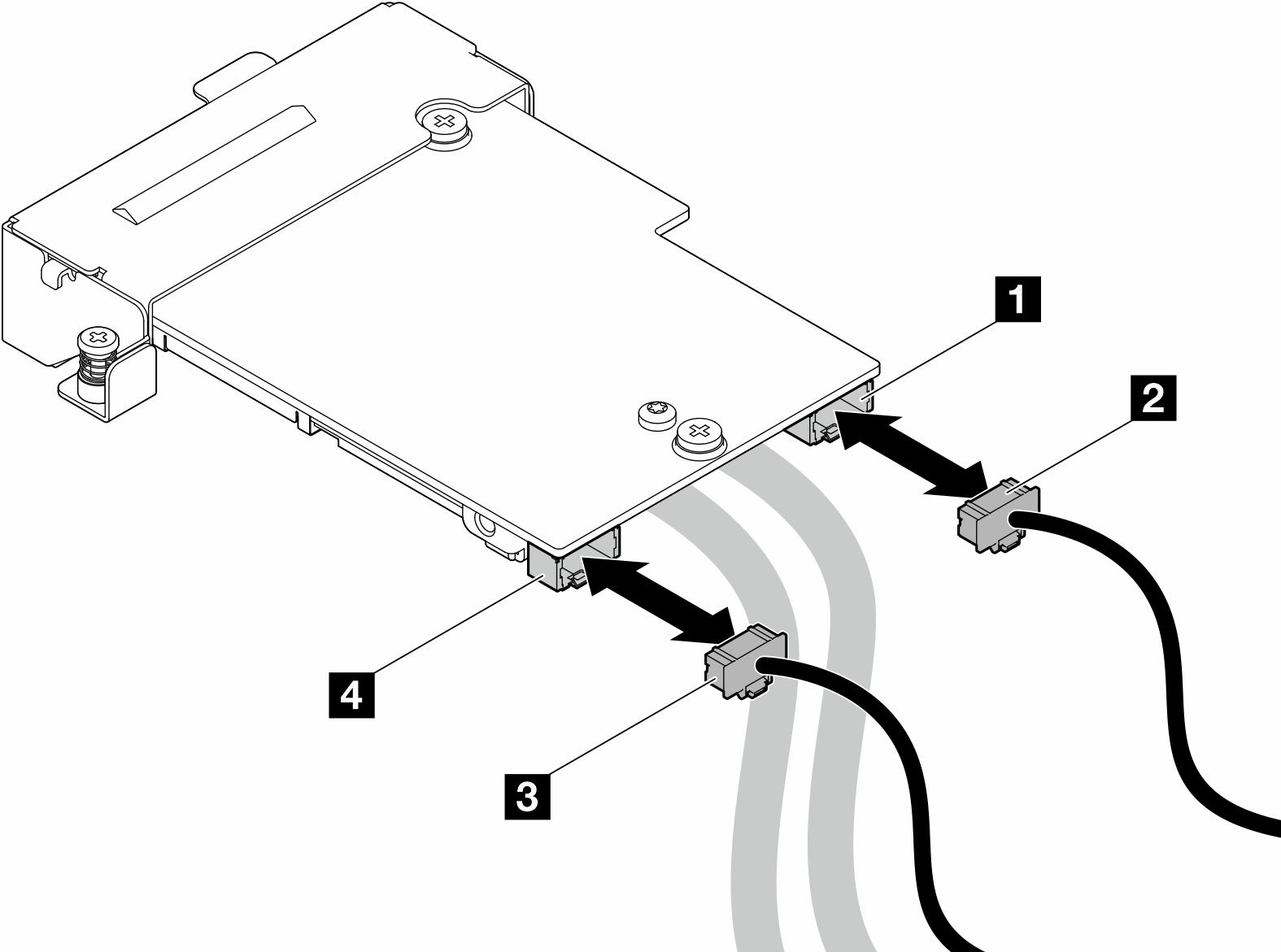
Figure 6. Disconnecting OSFP module cables from the network board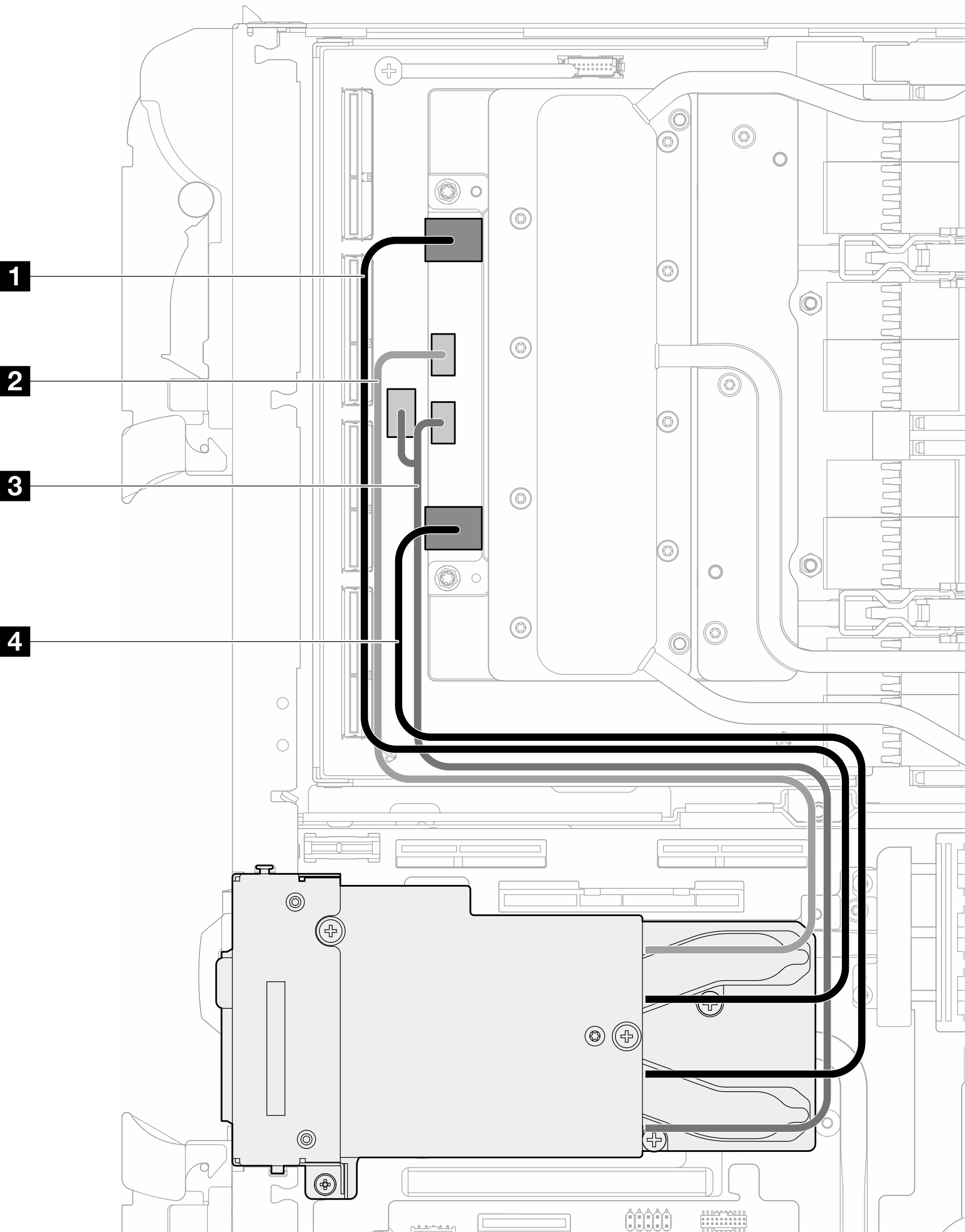
Cable From OSFP module connectors
To Network board connectors
1 Network cable (long) Network connector (near GPU node) Port 0 2 Power cable Power connector P1 OOB port 0 3 Power cable Power connector P2 OOB port 1 (on network board) and power connector (on carrier board) 4 Network cable (short) Network connector (near Compute node) Port 1 - Remove the three screws from the OSFP module.Figure 7. Removing the OSFP module
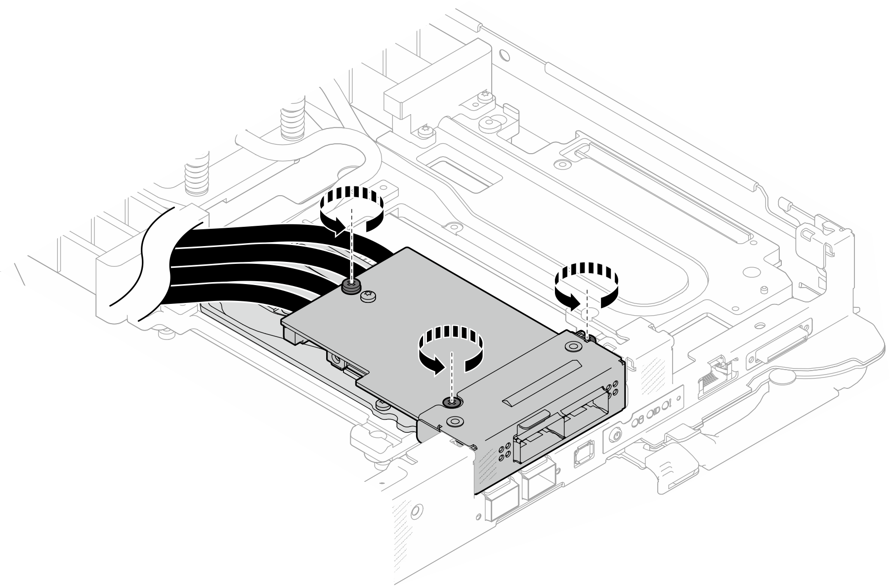
- Remove the OSFP module.
 Insert a flat head screwdriver into the gap between the OSFP module and the OSFP module conduction plate; then, rotate the flat head screwdriver to release the OSFP module from the conduction plate.
 Carefully hold the OSFP module by its edges and keep the OSFP module at an angle. Then, remove it from the compute node.
Figure 8. Removing the OSFP module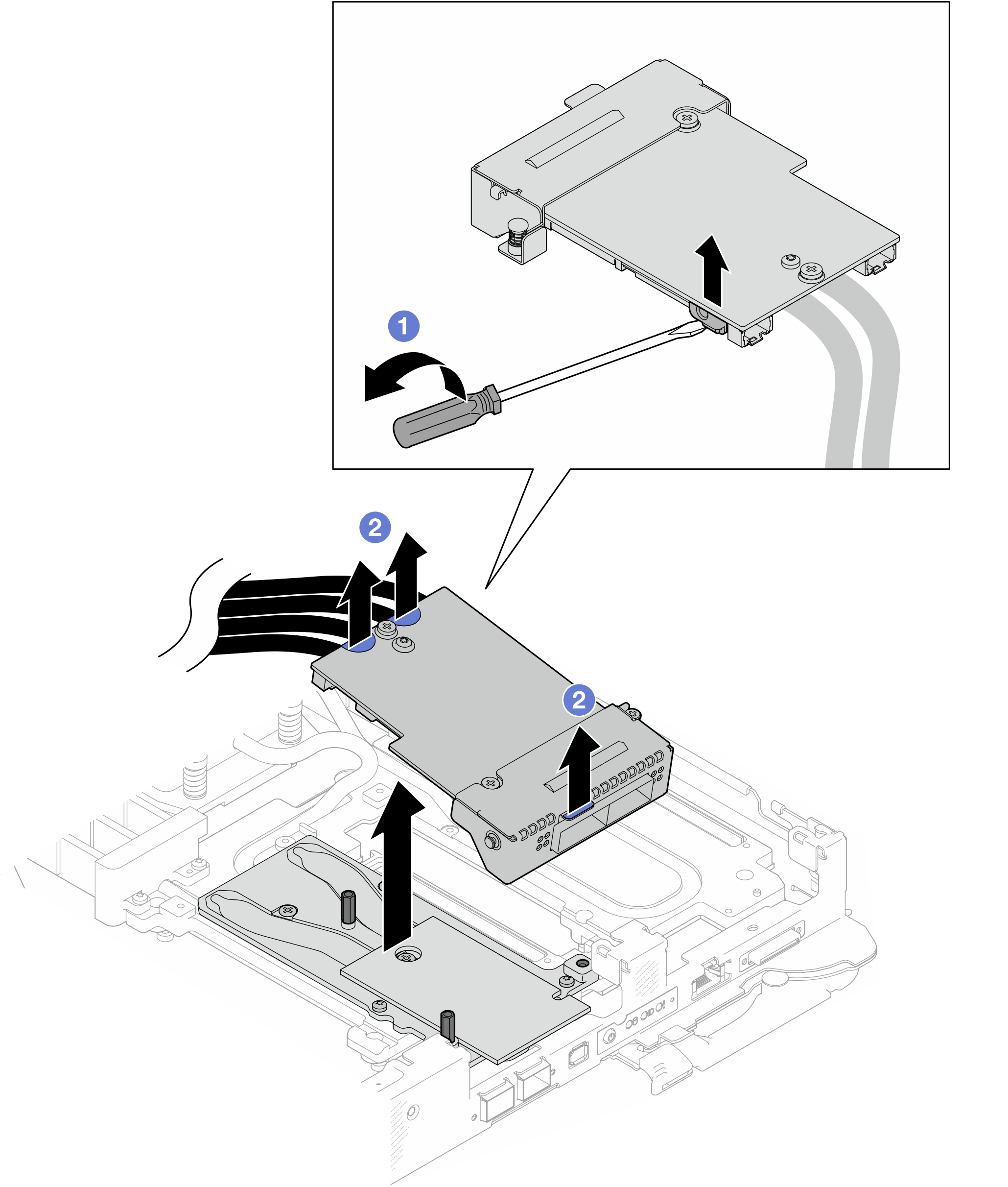
- Disconnect the power cables from the OSFP module.Figure 9. OSFP module power cables removal
Remove the network board
- Remove the carrier board power cable from the GPU node.Figure 10. Carrier board power cable removal
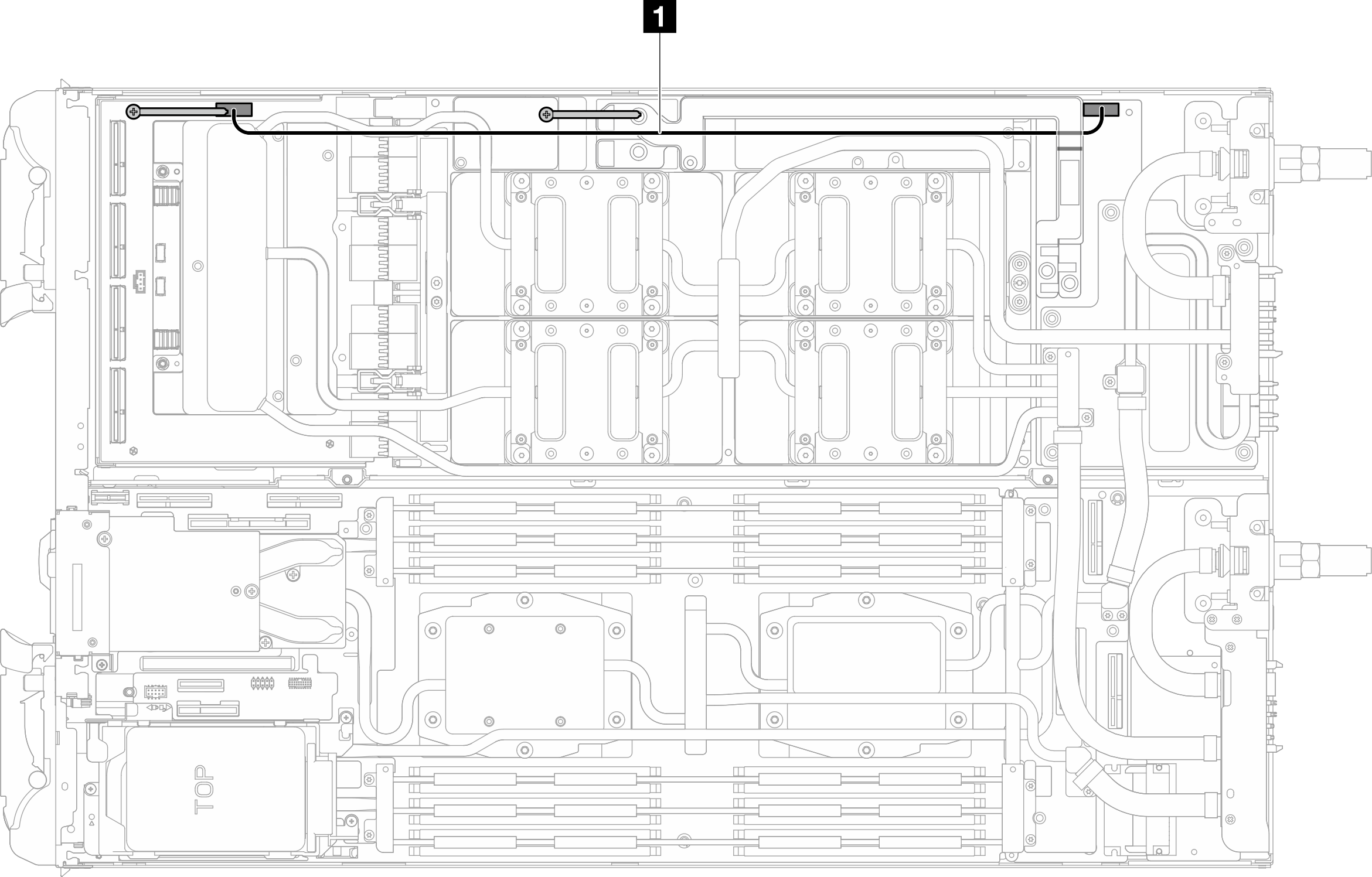
Cable From (carrier board) To (GPU node power distribution board) 1 Carrier board power cable Power and side band connector Power connector - Remove cable tie from the GPU board.Figure 11. Cable tie removal
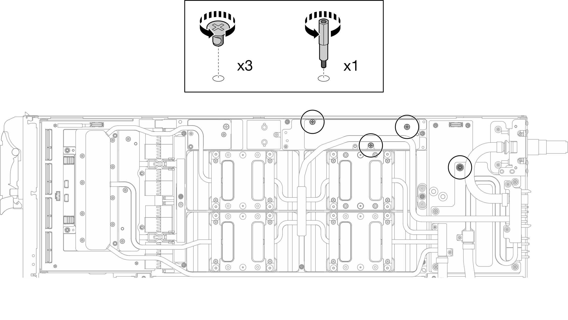
- Remove the Hex screw (x1) and the PH1 screws (x3) from the water loop with a torque screwdriver set to the proper torque.NoteFor reference, the torque required for the screws to be fully tightened/removed is 5.0+/- 0.5 lbf-in, 0.55+/- 0.05 N-M.Figure 12. Water loop Hex and PH1 screws removal (GPU node)
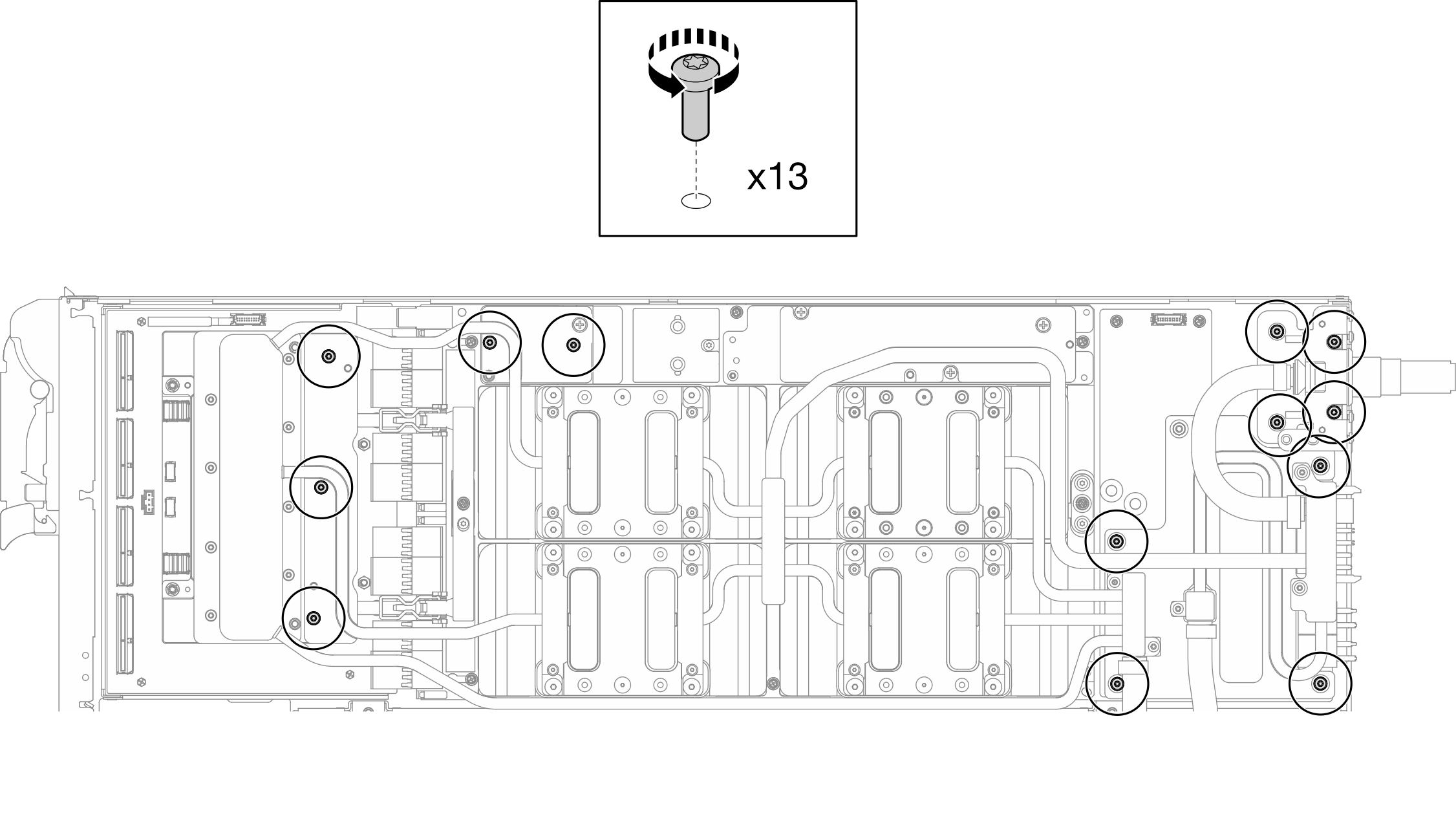
- Remove water loop screws and quick connect screws (x13 Torx T10 screws) with a torque screwdriver set to the proper torque.NoteFor reference, the torque required for the screws to be fully tightened/removed is 5.0+/- 0.5 lbf-in, 0.55+/- 0.05 N-M.Figure 13. Water loop Torx T10 screws removal (GPU node)
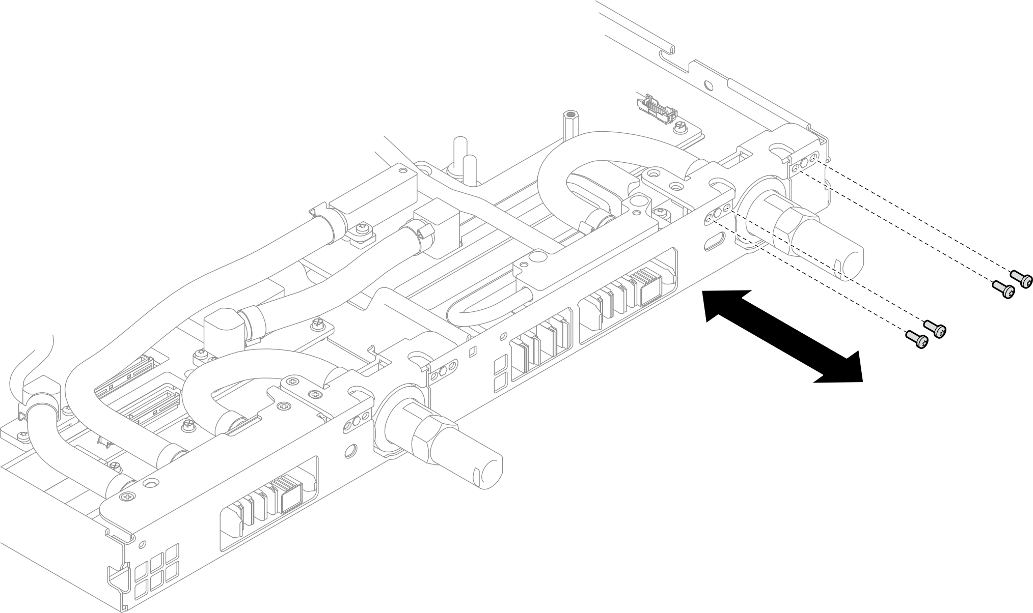
- Remove the quick connect screws (x4 Torx T10) with a torque screwdriver set to the proper torque.NoteFor reference, the torque required for the screws to be fully tightened/removed is 5.0+/- 0.5 lbf-in, 0.55+/- 0.05 N-M.Figure 14. Quick connect screw removal (GPU node)
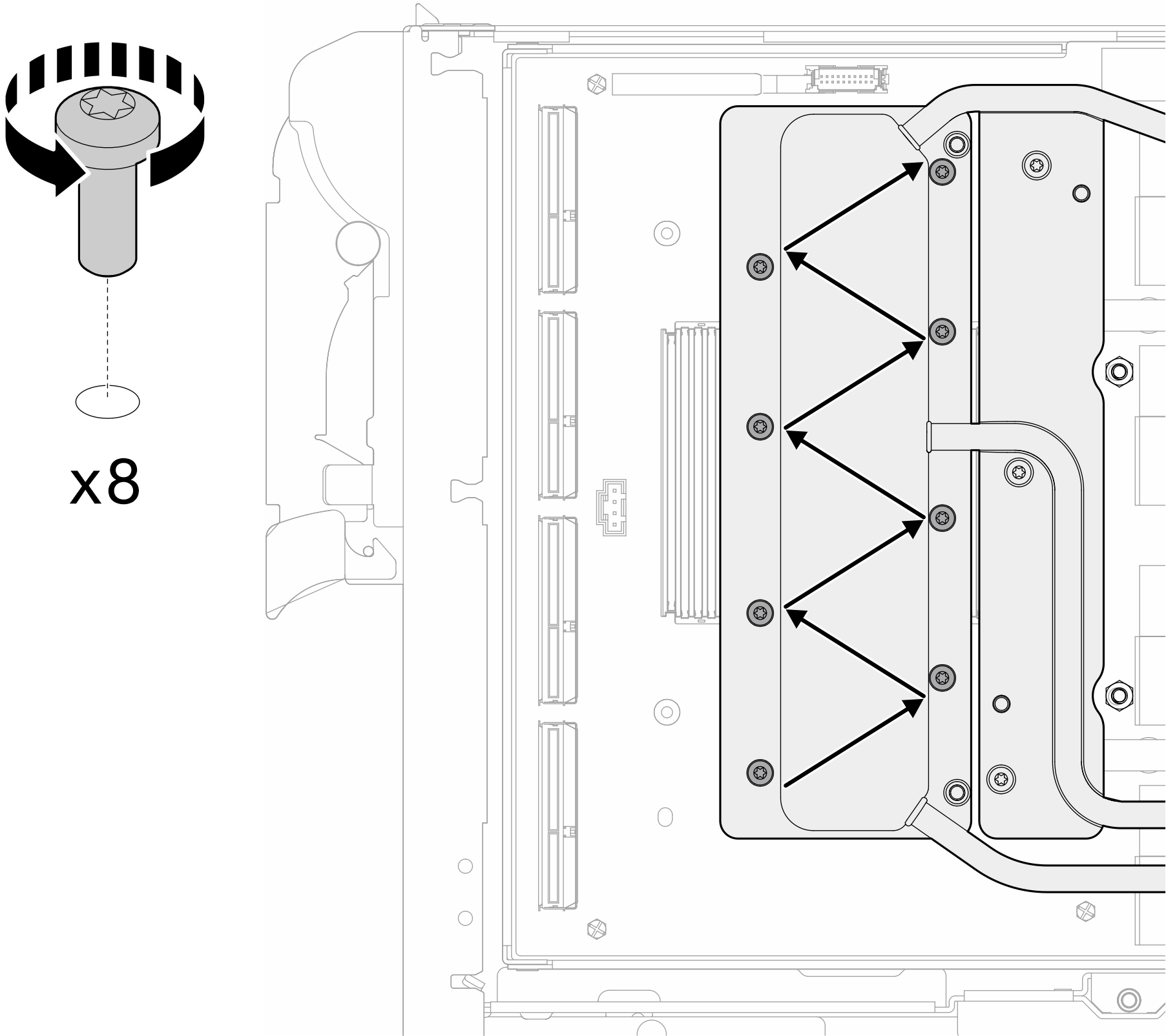
- Follow the screw removal sequence specified on the network board label, and remove network cold plate screws (x8 Torx T10 screws) with a torque screwdriver set to the proper torque.NoteFor reference, the torque required for the screws to be fully tightened/removed is 5.0+/- 0.5 lbf-in, 0.55+/- 0.05 N-M.Figure 15. Network card screw removal
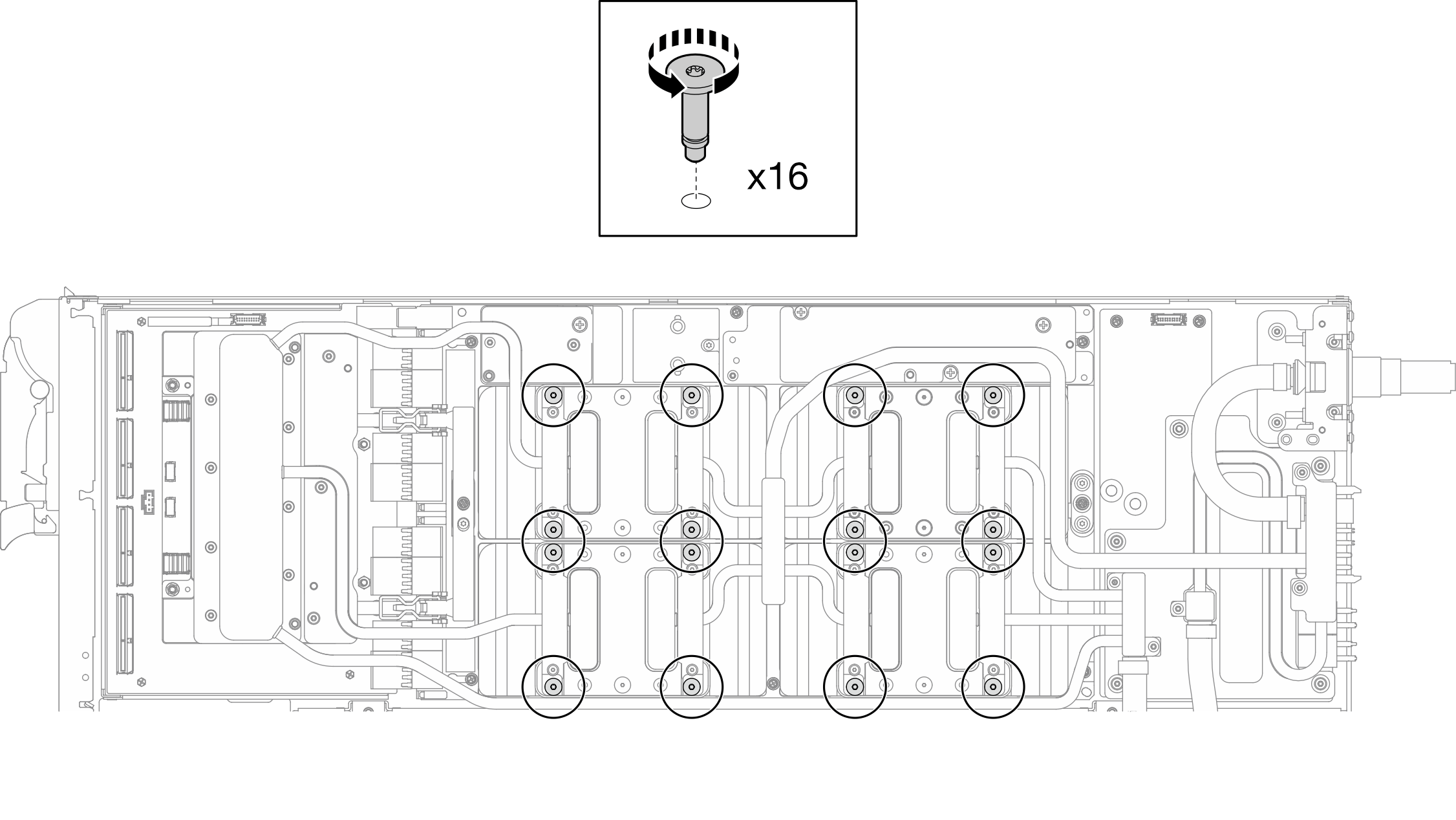
- Loosen GPU cold plate screws (x16 Torx T10 screws) in the diagonal pattern with a torque screwdriver set to the proper torque.NoteFor reference, the torque required for the screws to be fully tightened/loosened is 3.5 +/- 0.5 lb-In (0.4 +/ -0.06 N-m).Figure 16. Loosening GPU cold plate screw
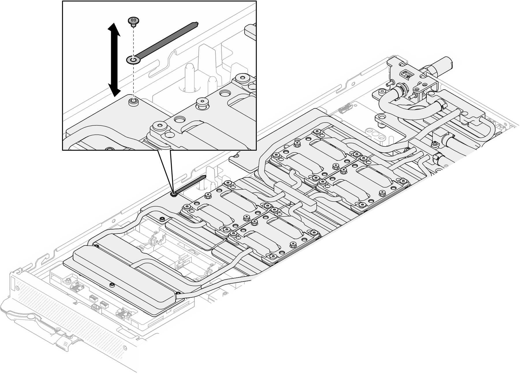
- Release the front and rear MISC conduction plates of the water loop from the GPU board.
- Insert a flat head screwdriver into the gaps between the MISC conduction plates (front and rear) and the GPU board. Then, slightly rotate the flat head screwdriver.NoteLocations of the gaps for inserting flat head screwdriver is shown in the illustration below.
- The front and rear MISC conduction plates release from the GPU board slightly.Figure 17. Releasing the front and rear MISC conduction plates release from the GPU board
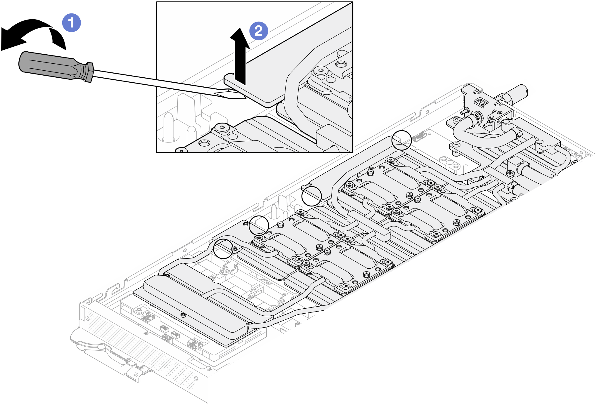
- Release the GPU cold plates from the GPUs.
- There are notches on the sides of the GPU cold plates for inserting a flat head screwdriver. The locations of the notches are shown in the illustration below.AttentionInserting the flat head screwdriver
ONLY to the notches circled in the illustration below. Otherwise, the screwdriver may damage the GPUs. Figure 18. Notches for releasing GPU cold plates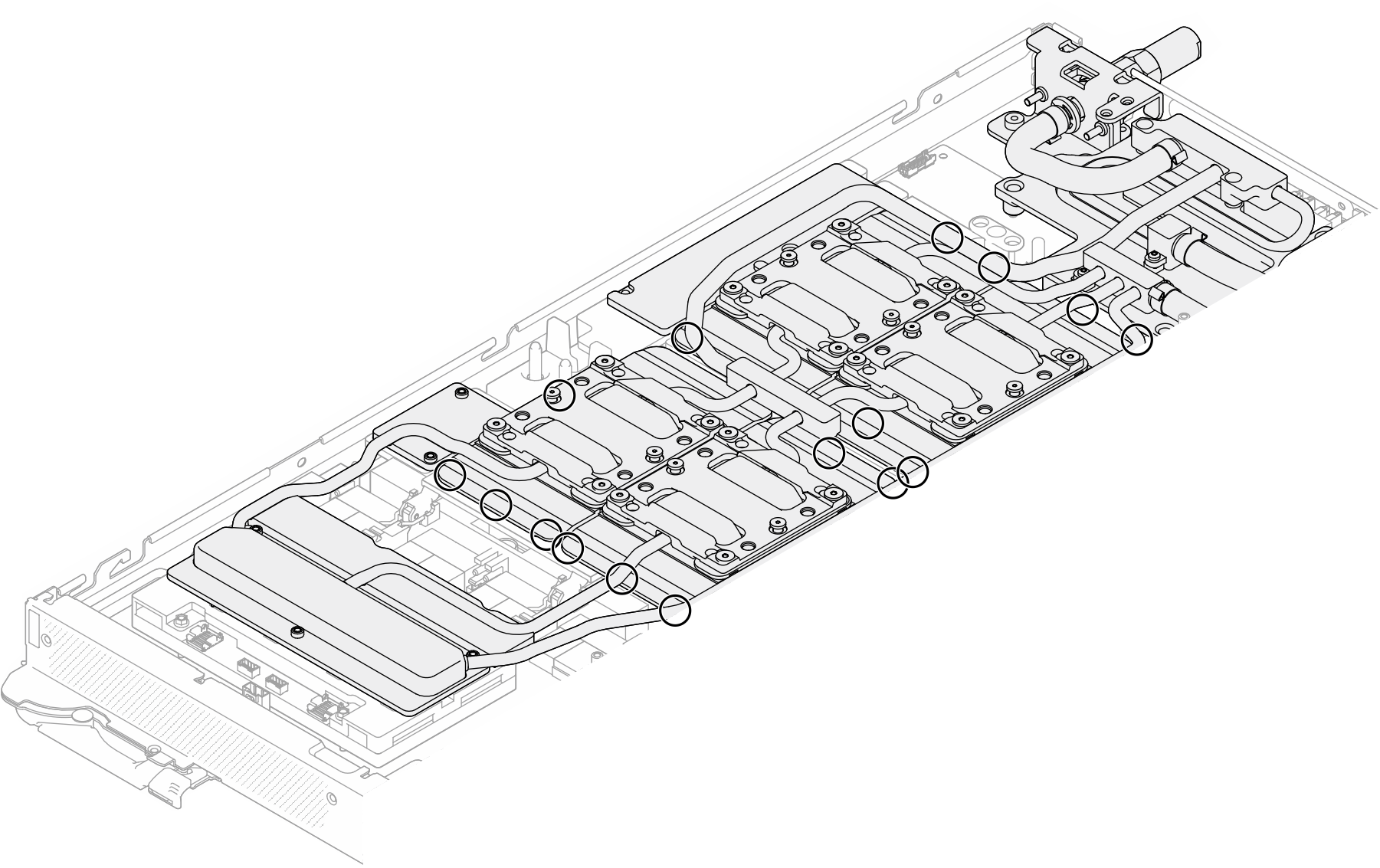
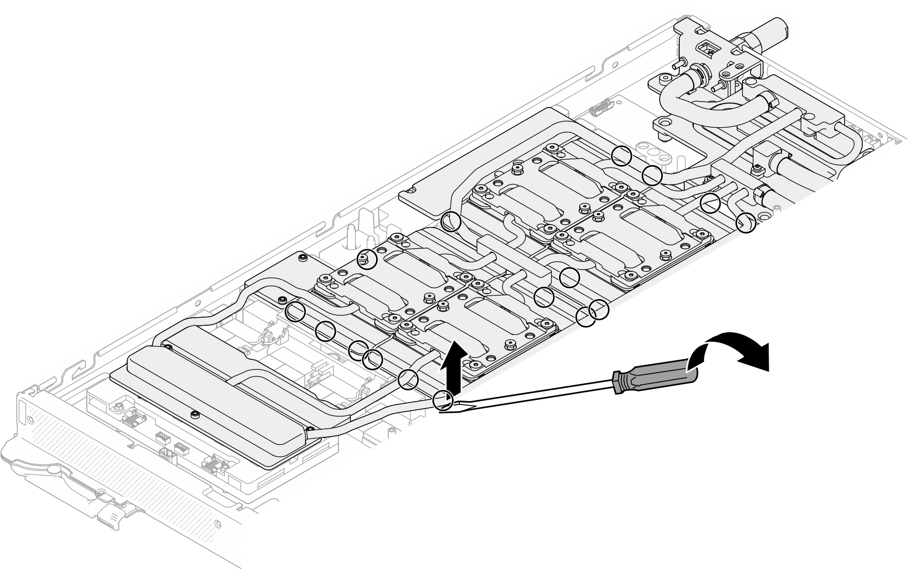
- Insert a flat screwdriver into all the notches shown in the illustration; then, slightly rotate the screwdriver to release the GPU cold plates from the GPUs.Figure 19. Releasing the GPU cold plate from the GPU
- There are notches on the sides of the GPU cold plates for inserting a flat head screwdriver. The locations of the notches are shown in the illustration below.
- Gently put the water loop carrier down onto the water loop and ensure it is seated firmly on the water loop.Figure 20. Water loop carrier installation (GPU node)
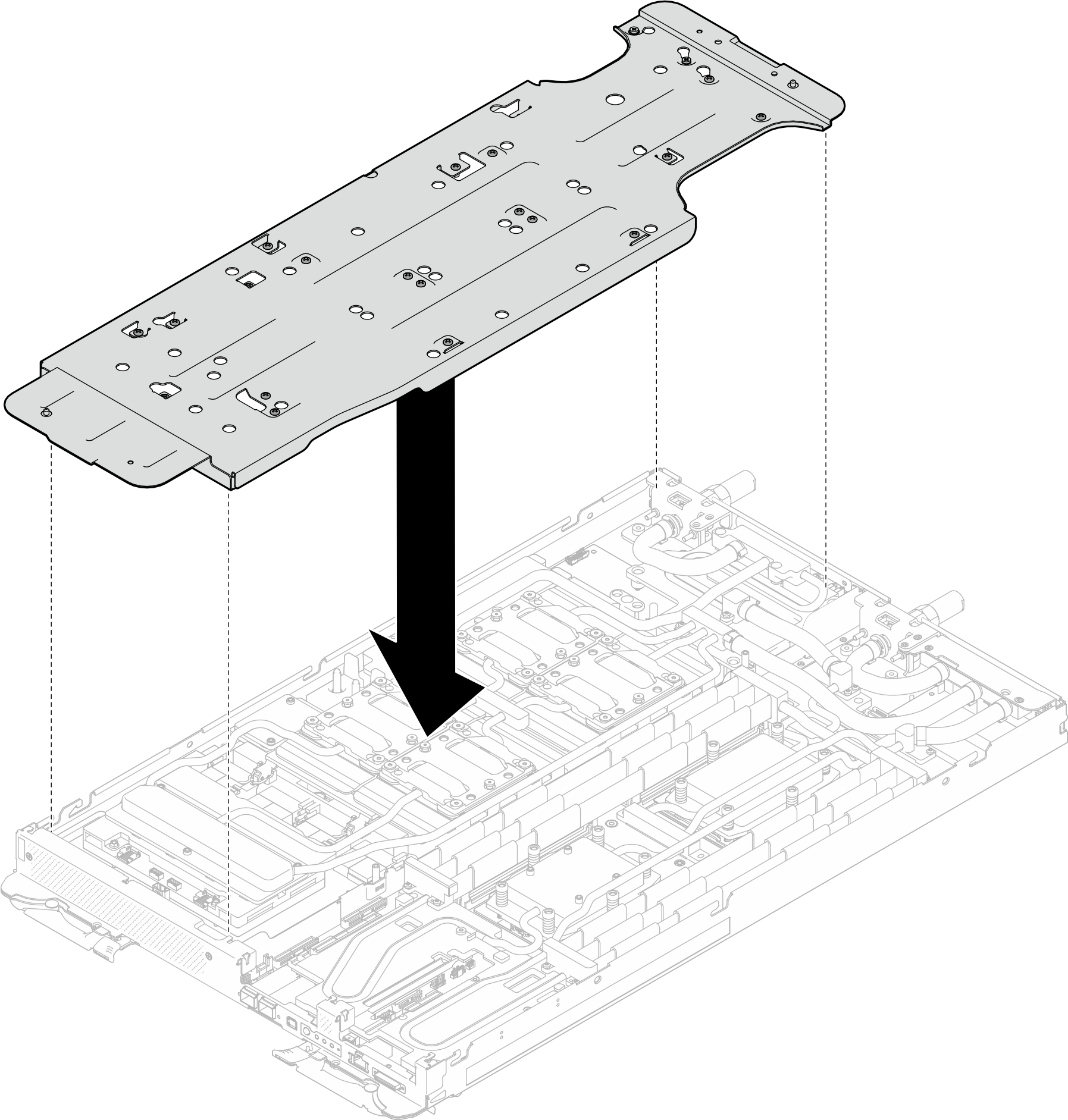
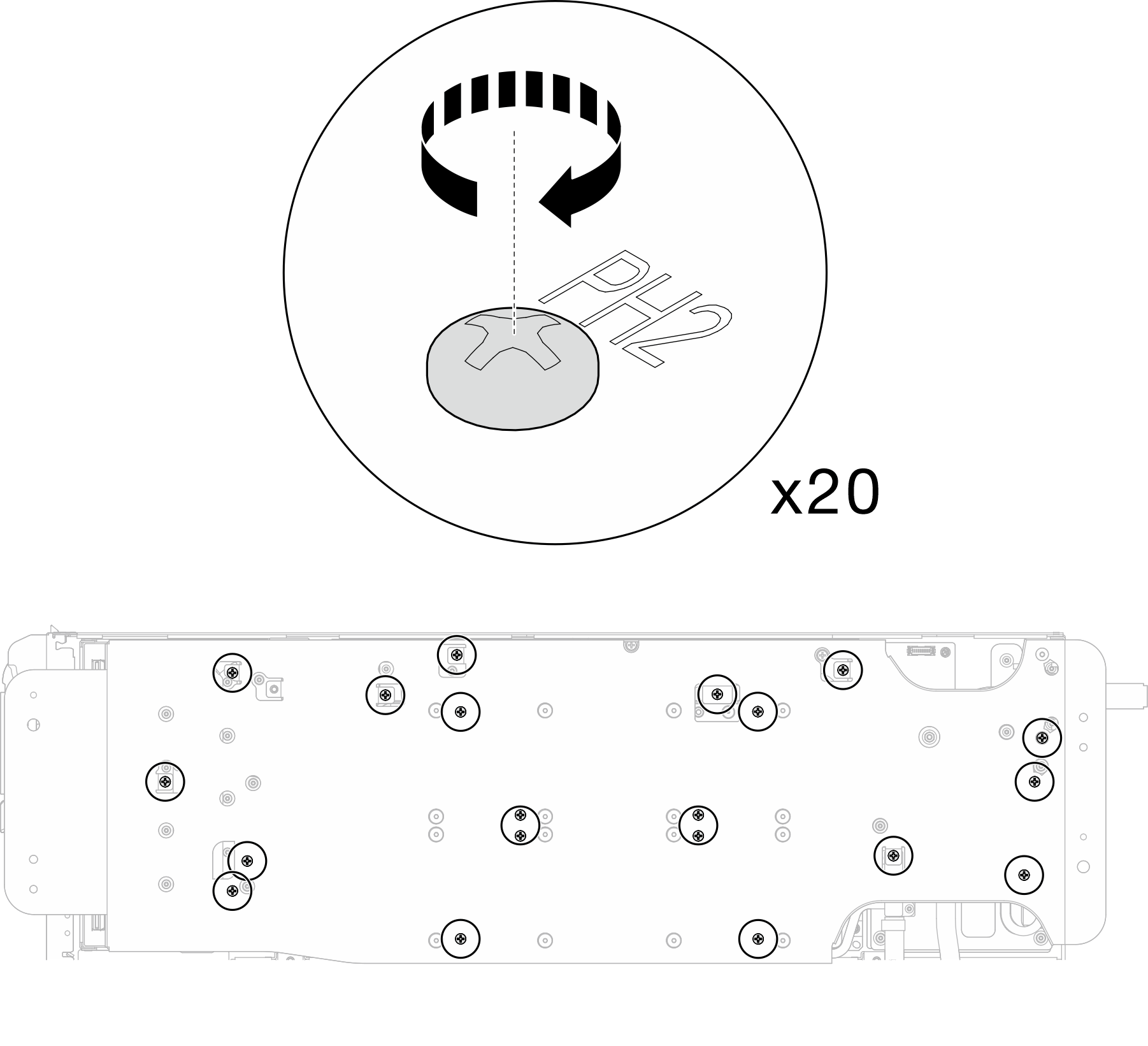
- Tighten water loop carrier screws (x20 Phillips #2 screws) with a torque screwdriver set to the proper torque.NoteFor reference, the torque required for the screws to be fully tightened/removed is 5.0+/- 0.5 lbf-in, 0.55+/- 0.05 N-M.Figure 21. Water loop screw and quick connect screw removal (GPU node)
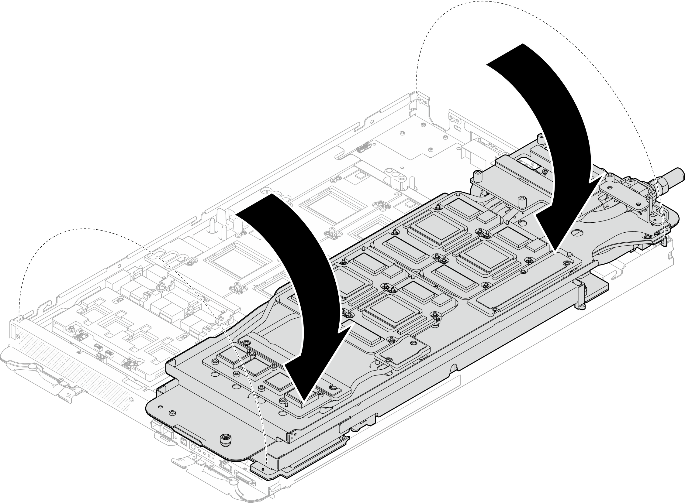
- Carefully rotate the GPU node side water loop so that it is sitting on top of the Compute node side water loop.Figure 22. Folding the GPU node side water loop onto the Compute node side water loop
- Immediately clean the PCM off all the GPUs with alcohol cleaning pads. Gently clean the PCM to avoid GPU damages.Attention
It is recommended to clean the PCM while it is in liquid state.
The electrical components around the die on the GPUs are extremely delicate. When removing the PCM and cleaning the GPU die, avoid touching the electrical components to prevent damages.
Figure 23. Cleaning PCM off from all GPUs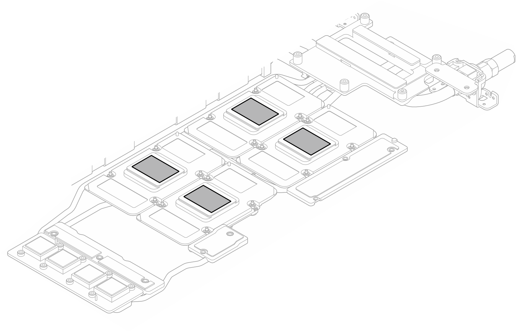
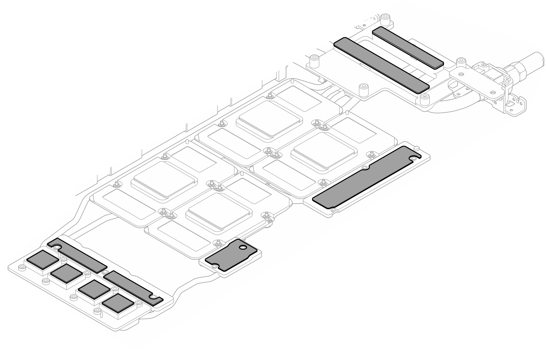
- With alcohol cleaning pads, wipe off any remaining putty pad and PCMs from the water loop and components in the GPU node.Figure 24. Cleaning putty pads from water loop
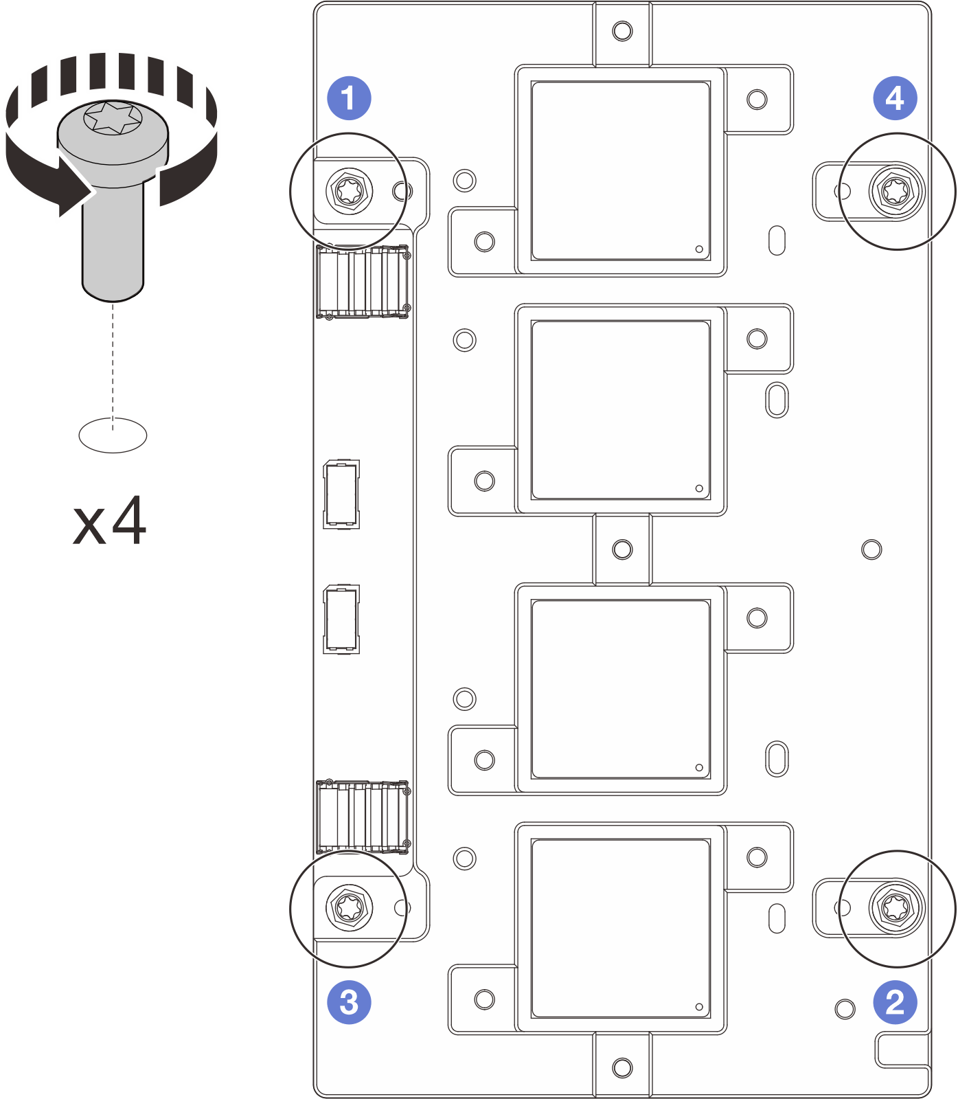
- Follow the sequence shown in the illustration below to remove the network board screws (x4 Torx T15 screws) with a torque screwdriver set to the proper torque.NoteFor reference, the torque required for the screws to be fully tightened/removed is 0.9 newton-meters, 7.96 inch-pounds.Figure 25. Network board screws removal
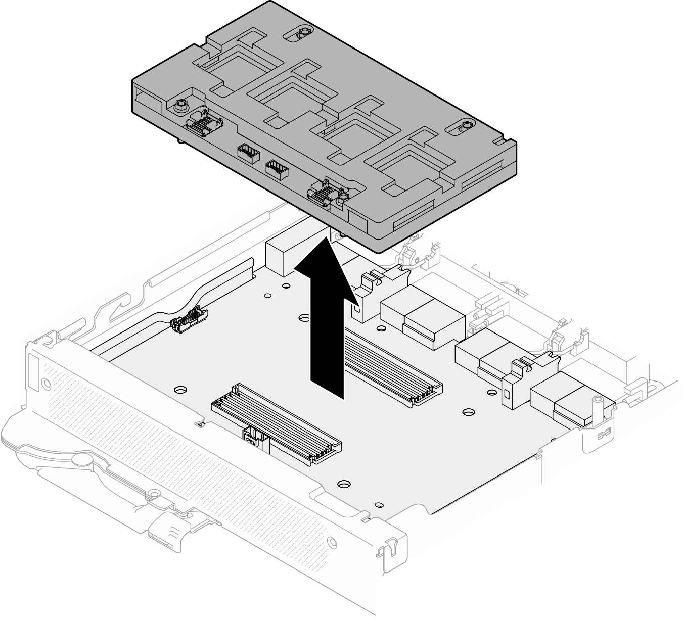
- Remove the network board from the GPU node.Figure 26. Removing the network board
If you are instructed to return the component or optional device, follow all packaging instructions, and use any packaging materials for shipping that are supplied to you.
Demo video