Install a PCIe adapter
Use this information to install a PCIe adapter.
About this task
Read Installation Guidelines and Safety inspection checklist to ensure that you work safely.
Go to Drivers and Software download website for ThinkSystem SD665 V3 to see the latest firmware and driver updates for your server.
Go to Update the firmware for more information on firmware updating tools.
- A video of this procedure is available at YouTube.
Procedure
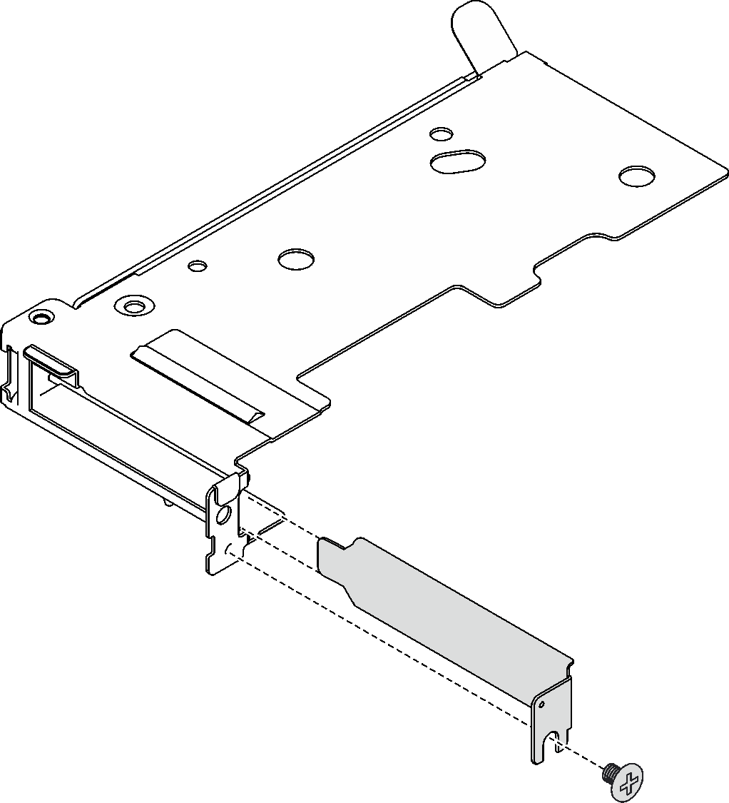
- If a filler is installed, remove the screw and remove the filler out of the PCIe riser-cage.Figure 1. Filler removal
- For shared I/O or socket direct configurations, connect the cable.
 Gently push the connectors into the slots.
 Close the cable covers and slightly press the cable covers until they click into place.
 On the side without the copper tubing of the PCIe adapter, insert the two latches into the slots next to the connectors.
 Close the cable clip covers and slightly press them to secure the connectors.
Figure 2. PCIe adapter cable installation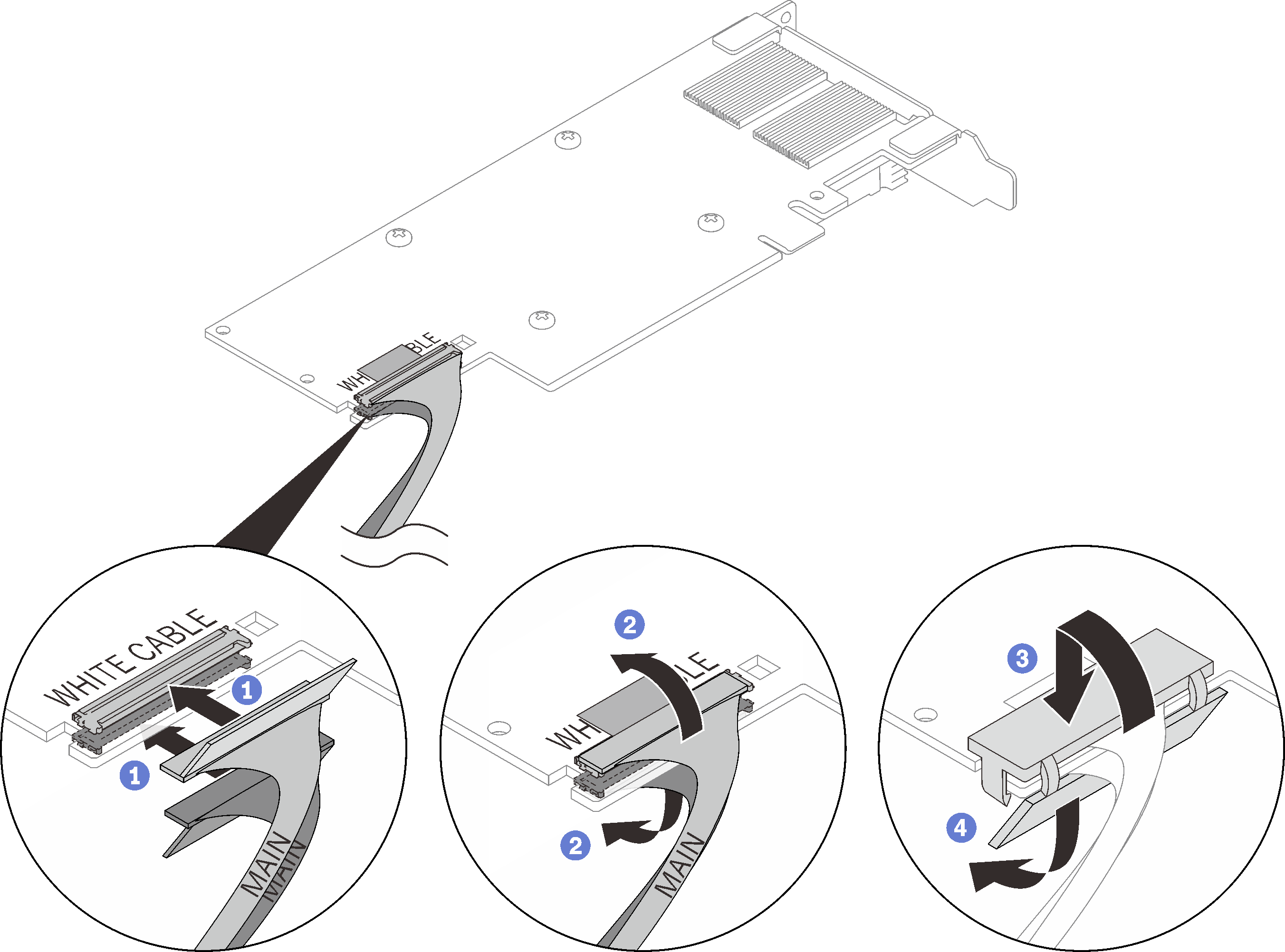 AttentionThere are
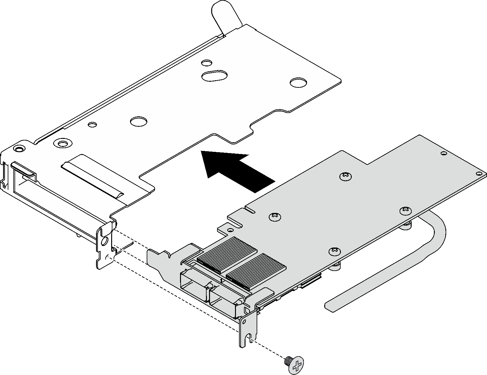
WHITE CABLE and BLACK CABLE callouts on the adapter, connect the cables to the connectors according to the cable colors. - Align the adapter with the PCIe slot on the riser-cage; then, carefully press the adapter straight into the slot until it is securely seated. Fasten the screw to secure the adapter.Figure 3. PCIe adapter installation
Install the PCIe riser assembly. See Install a PCIe riser assembly (ConnectX-6) , Install a PCIe riser assembly (ConnectX-7 NDR 200), or Install a PCIe riser assembly (ConnectX-7 NDR 400).
Install the cross braces. See Install the cross braces.
Install the tray cover. See Install the tray cover.
Install the tray into the enclosure. See Install a DWC tray in the enclosure.
- Connect all required external cables to the solution.NoteUse extra force to connect QSFP cables to the solution.
Check the power LED on each node to make sure it changes from fast blink to slow blink to indicate all nodes are ready to be powered on.
Demo video