Install a PCIe riser assembly (ConnectX-7 NDR 200)
Use this information to install a PCIe riser assembly with ConnectX-7 NDR 200 adapter.
About this task
To identify the gap pad/putty pad location and orientation, see:
Required Tools list in the following section.
Before replacing the gap pad/putty pad, gently clean the interface plate or the hardware surface with an alcohol cleaning pad.
Hold the gap pad/putty pad carefully to avoid deformation. Make sure no screw hole or opening is blocked by the gap pad/putty pad material.
Do not use expired putty pad. Check the expiry date on putty pad package. If the putty pads are expired, acquire new ones to properly replace them.
Required tools
Make sure you have the ConnectX-7 NDR200 Putty Pad Kit to properly replace the component. Putty pad cannot be reused. Whenever a component is removed, putty pads must be replaced with new ones before reinstalling the component.
Read Installation Guidelines and Safety inspection checklist to ensure that you work safely.
Turn off the corresponding DWC tray that you are going to perform the task on.
Disconnect all external cables from the enclosure.
Use extra force to disconnect QSFP cables if they are connected to the solution.
For more information on selecting riser slot for PCIe riser installation, see Internal cable routing.
Go to Drivers and Software download website for ThinkSystem SD665 V3 to see the latest firmware and driver updates for your server.
Go to Update the firmware for more information on firmware updating tools.
Procedure
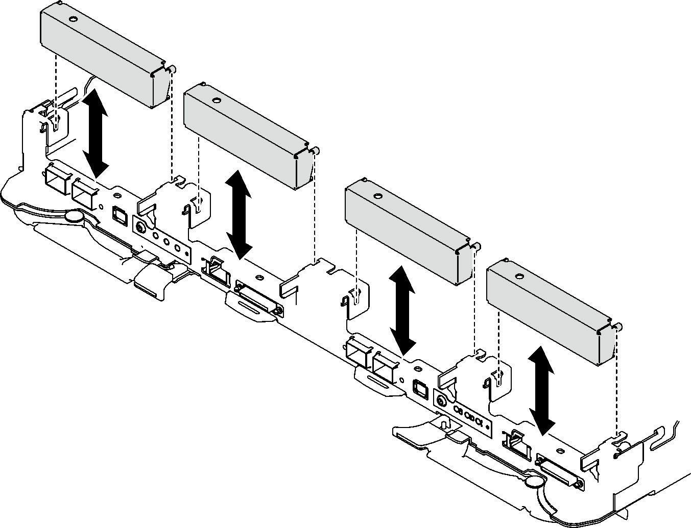
- Remove the blank bezel fillers if they are installed.Figure 2. Blank bezel filler removal
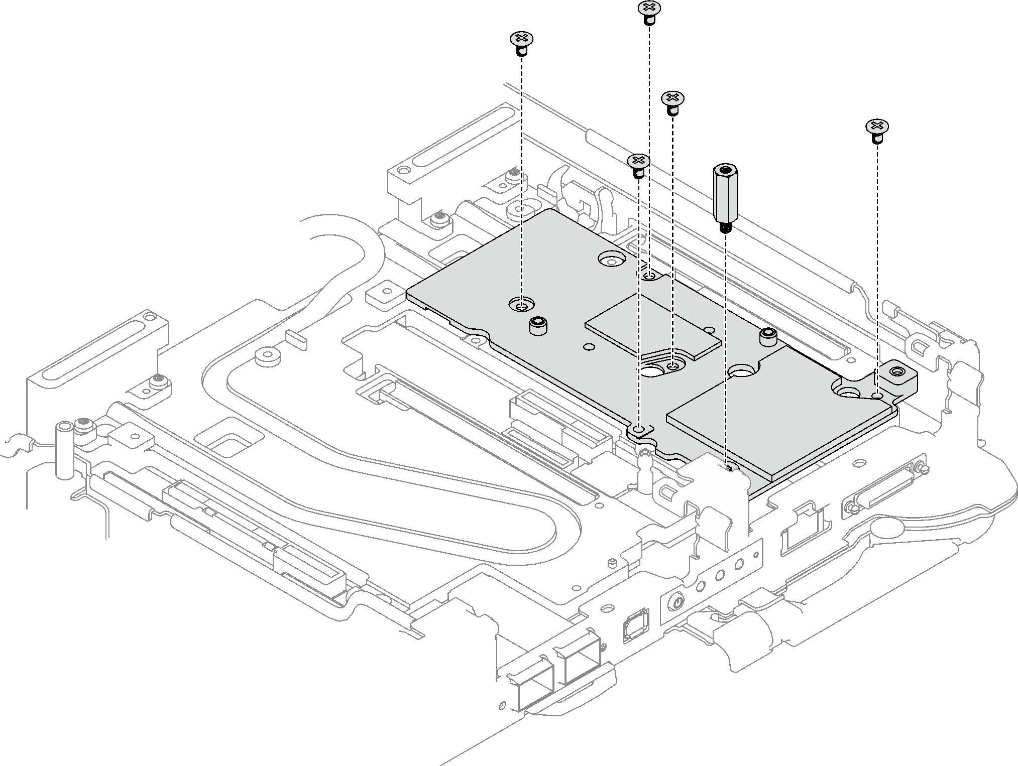
- If the interface plate was removed, place the interface plate onto the node; then, secure the interface plate with five Phillips #2 screws.Figure 3. Interface plate installation
- Replace the interface plate putty pad with a new one. Make sure to follow Gap pad/putty pad replacement guidelines.Attention
Putty pad cannot be reused. Whenever a component is removed, putty pads must be replaced with new ones before reinstalling the component.
Figure 4. Interface pad on cold plate for CX-7 NDR 200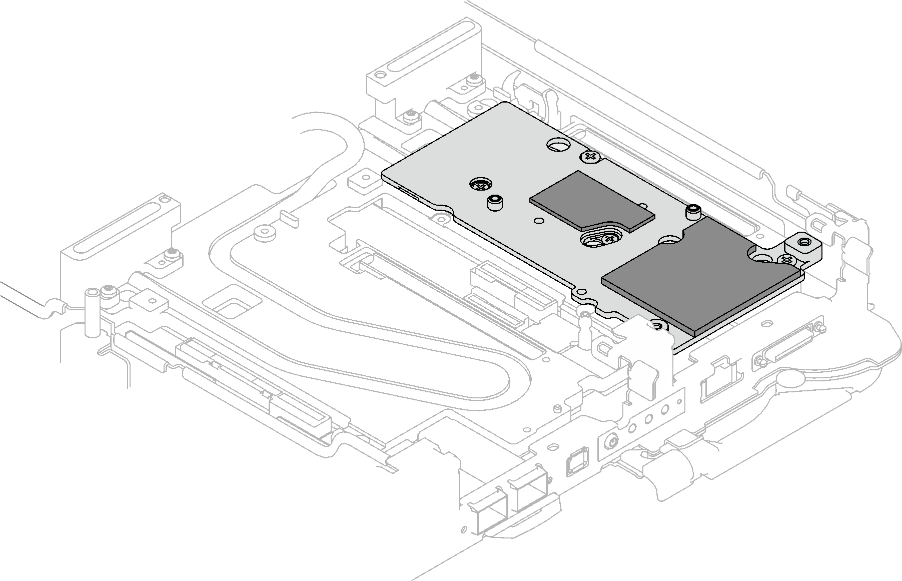
- Install the PCIe riser assembly.
 Install one hex standoff screw to the cold plate.
 Align the tab on the PCIe riser assembly with the slot on the front of the node; then, insert the PCIe riser assembly onto the system board.
 Secure the riser assembly with one screw.
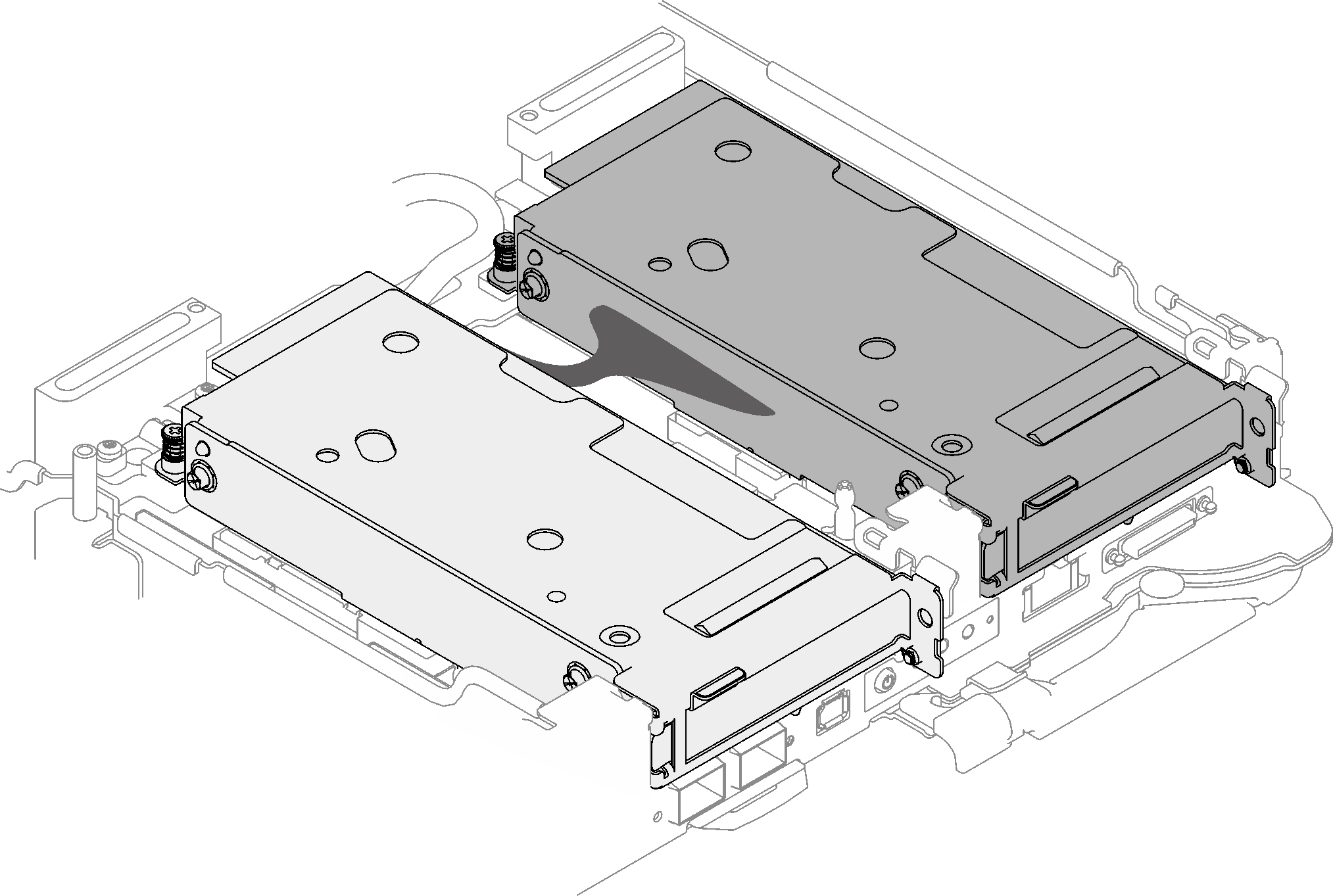
Figure 5. PCIe riser assembly installation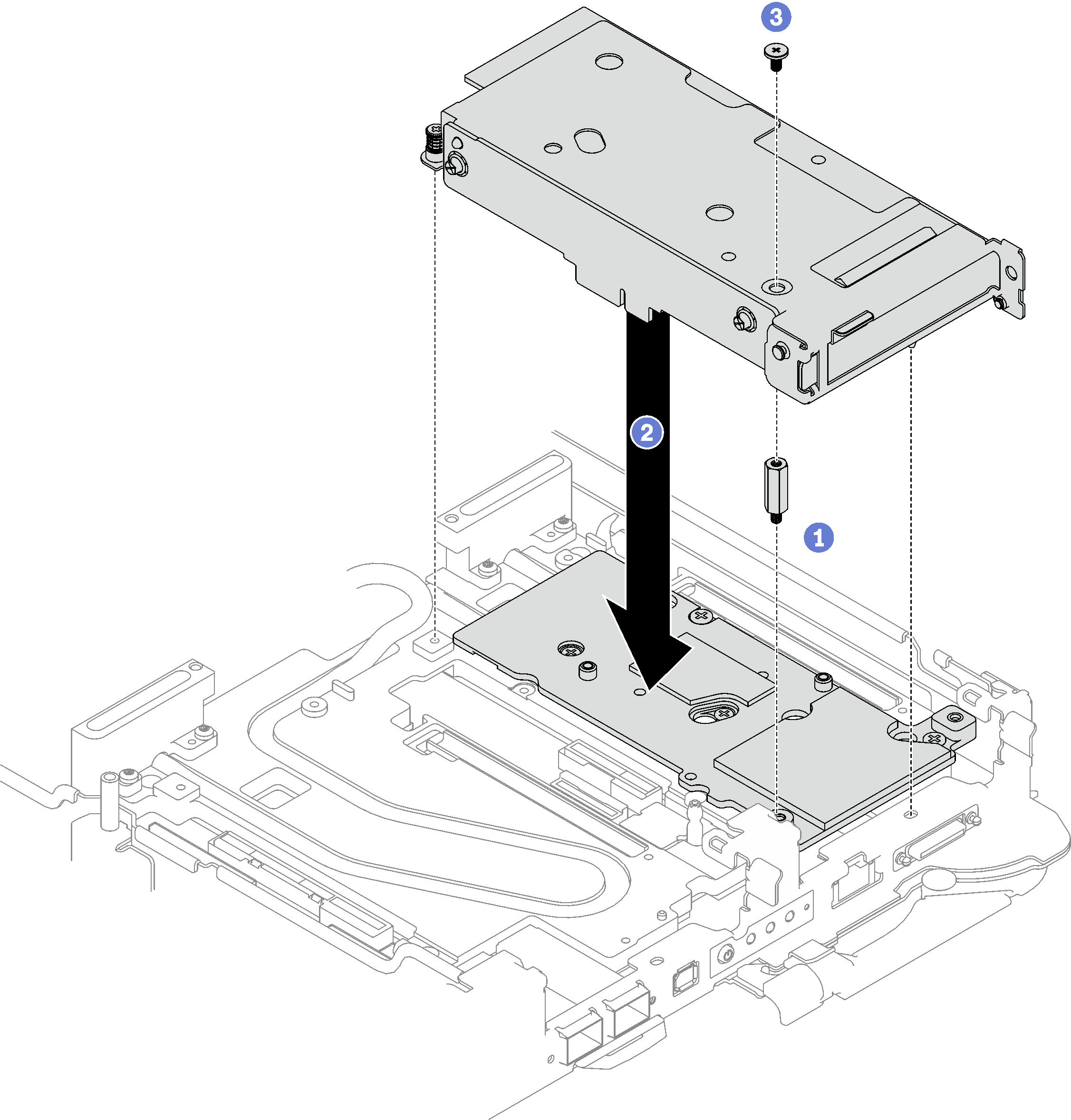
- Secure the PCIe riser assembly.
- Install the clamp bracket and fasten the captive screw.
- Fasten the captive screw on the PCIe riser assembly.
- Install two screws to secure the PCIe riser assembly.
Figure 6. Clamp bracket captive screw installation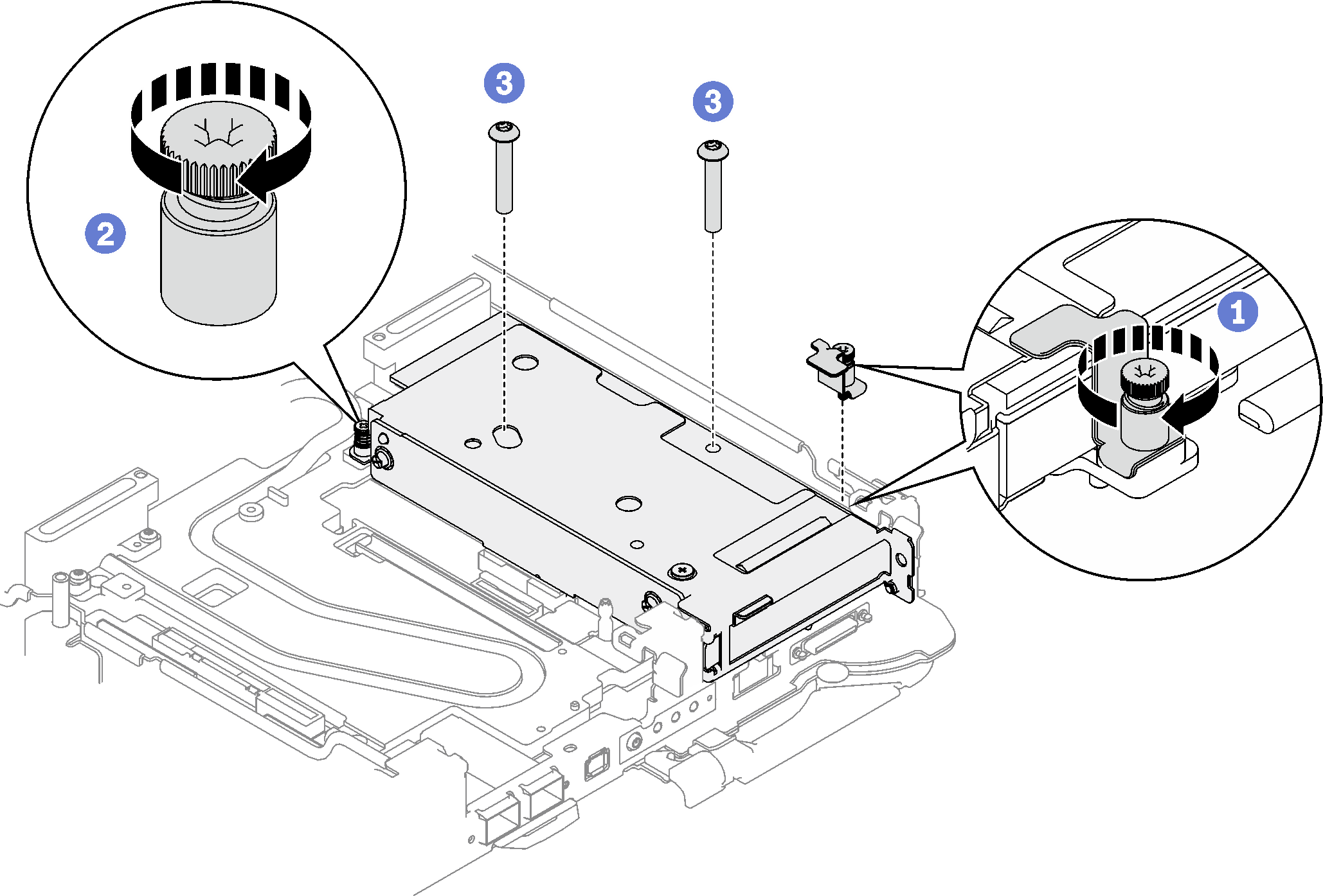
- If applicable, install the interconnect cable to the node.
- Place the two washers onto the water loop.
- Align the interconnect cable to the screw holes on the water loop.
- Install the two screws to secure the interconnect cable to the water loop.
Figure 7. Interconnect cable installation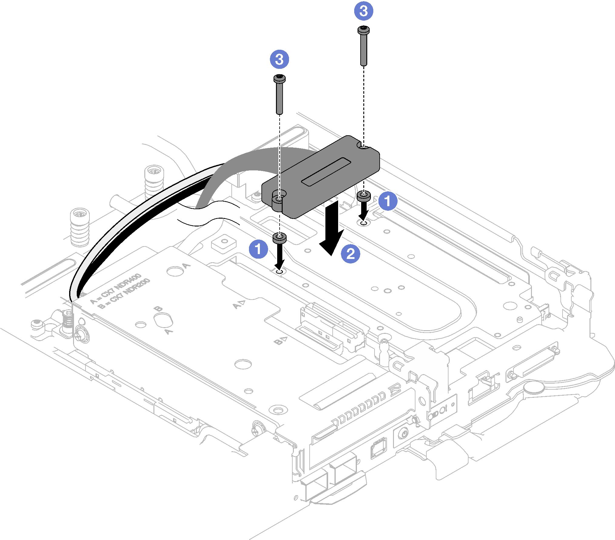
For shared I/O or socket direct configurations, route the cables. See Internal cable routing for cable routing details.
Install the cross braces. See Install the cross braces.
Install the tray cover. See Install the tray cover.
Install the tray into the enclosure. See Install a DWC tray in the enclosure.
- Connect all required external cables to the solution.NoteUse extra force to connect QSFP cables to the solution.
Check the power LED on each node to make sure it changes from fast blink to slow blink to indicate all nodes are ready to be powered on.
Demo video