Front LEDs
The following illustration shows LEDs on the front of the solution. By viewing the status of LEDs, you can often identify the source of the error.
Figure 1. Front LEDs
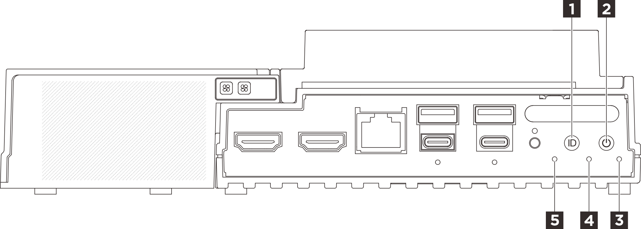
| 1 UID button with LED (blue) | 2 Power button with power status LED (green) |
| 3 Security LED (green) | 4 System Error LED (yellow) |
| 5 UART status LED (white) |
3 Security LED (green)
The states of Security LED are as following:
- Solid on: The server is operating with security feature enabled (SED enabled or intrusion enabled).
- Blinking: The server is in System Lockdown Mode. Activate or unlock the system for operation. See Activate or unlock the system.
- Off: System is activated but no security feature is enabled on the server.
4 System Error LED (yellow)
The system error LED helps you to determine if there are any system errors.
| Status | Color | Description | Action |
|---|---|---|---|
| On | Yellow | An error has been detected on the server. Causes might include one or more of the following errors:
| Check the Event log to determine the exact cause of the error. |
| Off | None | The server is off or the server is on and is working correctly. | None. |
5 UART status LED (white)
| Status | Color | Description |
|---|---|---|
| On | White | UART output with XCC log. |
| Off (Default) | None | UART output with CPU log. |
Give documentation feedback