Remove a node from the wall or the ceiling
Follow instructions in this section to remove a node from the wall or the ceiling.
About this task
Attention
Read Installation Guidelines and Safety inspection checklist to ensure that you work safely.
Reserve 500 mm of clearance in front of the node for installation/removal procedure.
Important
This task must be operated by trained technicians.
Note
Depending on the model, your server might look slightly different from the illustration.
Remove a node from the node sleeve
Procedure
- Power off the server and peripheral devices and disconnect the power cords and all external cables. See Power off the server.S002
 CAUTIONThe power-control button on the device and the power switch on the power supply do not turn off the electrical current supplied to the device. The device also might have more than one power cord. To remove all electrical current from the device, ensure that all power cords are disconnected from the power source.
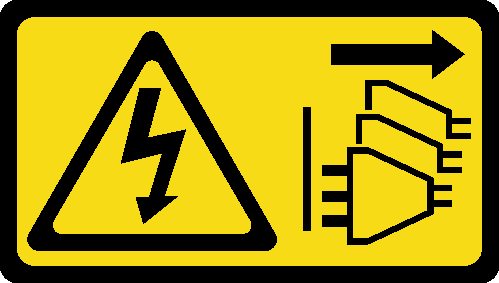
 - Remove the node from the node sleeve.
 Loosen the four thumbscrews on the side of the node sleeve.
 Slide the node out of the node sleeve.Figure 1. Removal of node from a node sleeve
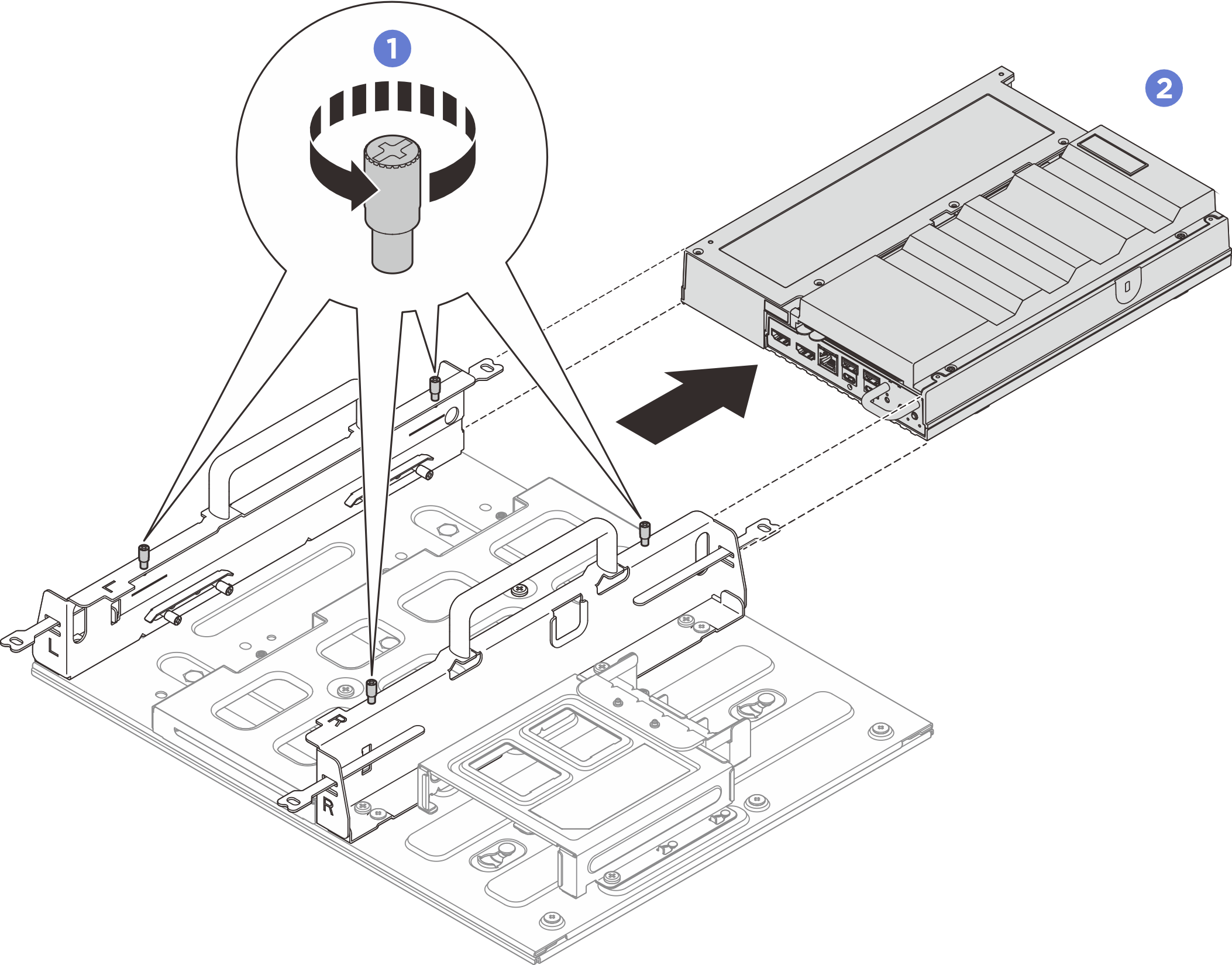
Remove the node sleeve assembly from the wall
Procedure
- Remove the node sleeve from the mount plate.
- Remove the eleven screws that secure the node sleeve.Figure 2. Removing the node sleeve with expansion kit
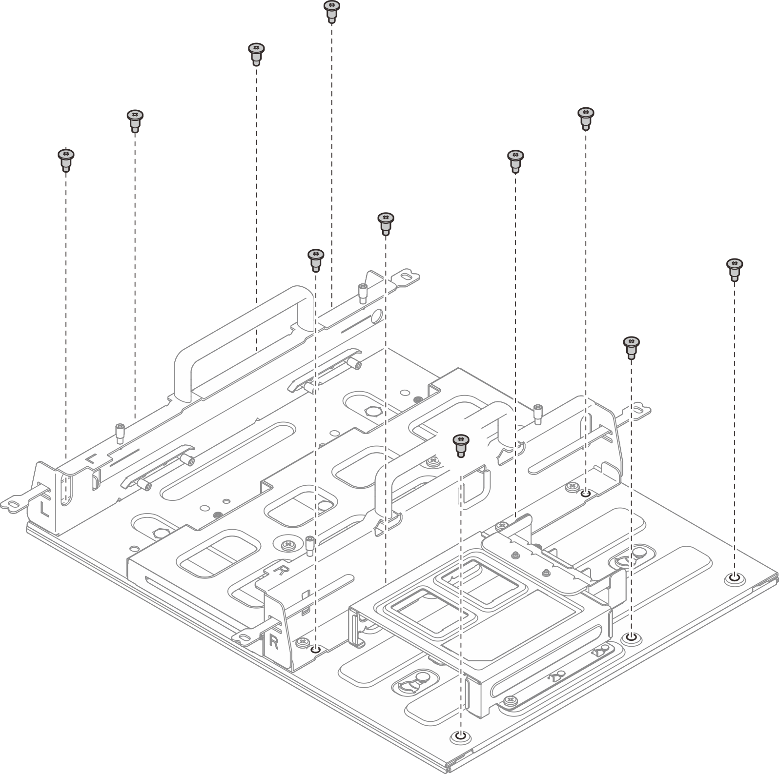 Figure 3. Removing the node sleeve without expansion kit
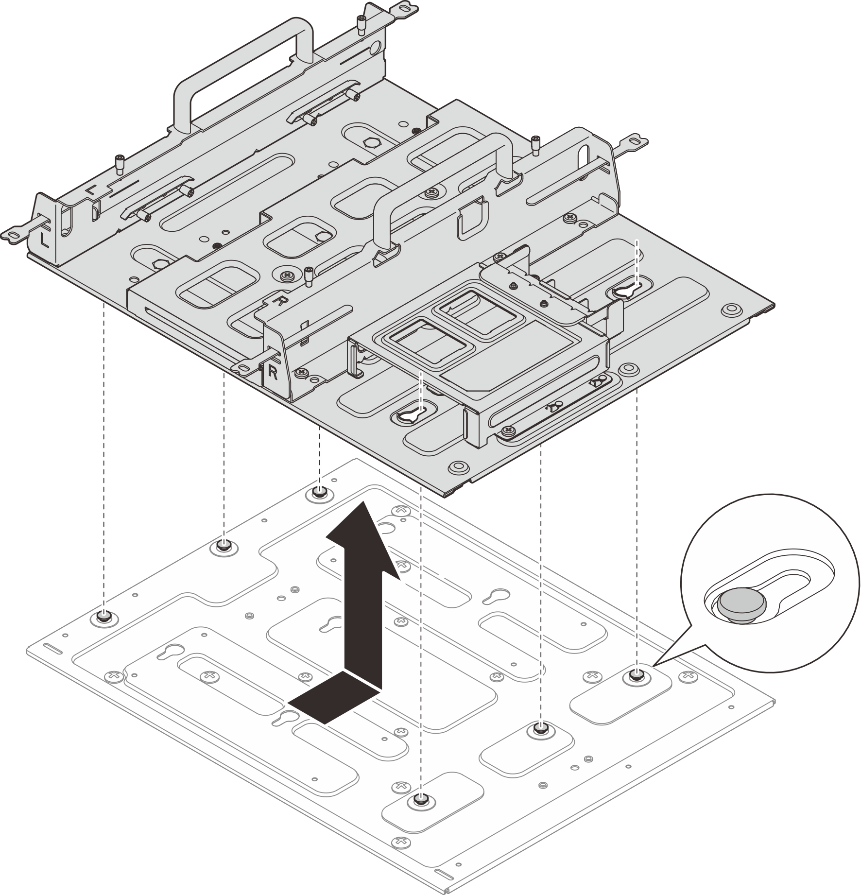
- Slide the node sleeve until the guide pins on the mount plate are seated in the large opening of the keyhole; then, remove the node sleeve from the mount plate.Figure 4. Removing the node sleeve
- Remove the eleven screws that secure the node sleeve.
- Loosen the four M4 screws and eight M6 screws that secure the mount plate; then, remove the mount plate from the wall.Figure 5. Removing the mount plate
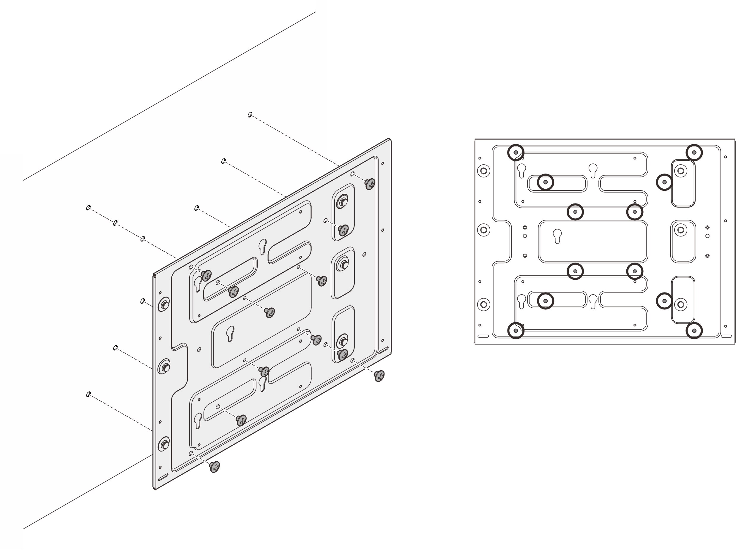 Figure 6. Locations of M4 screws
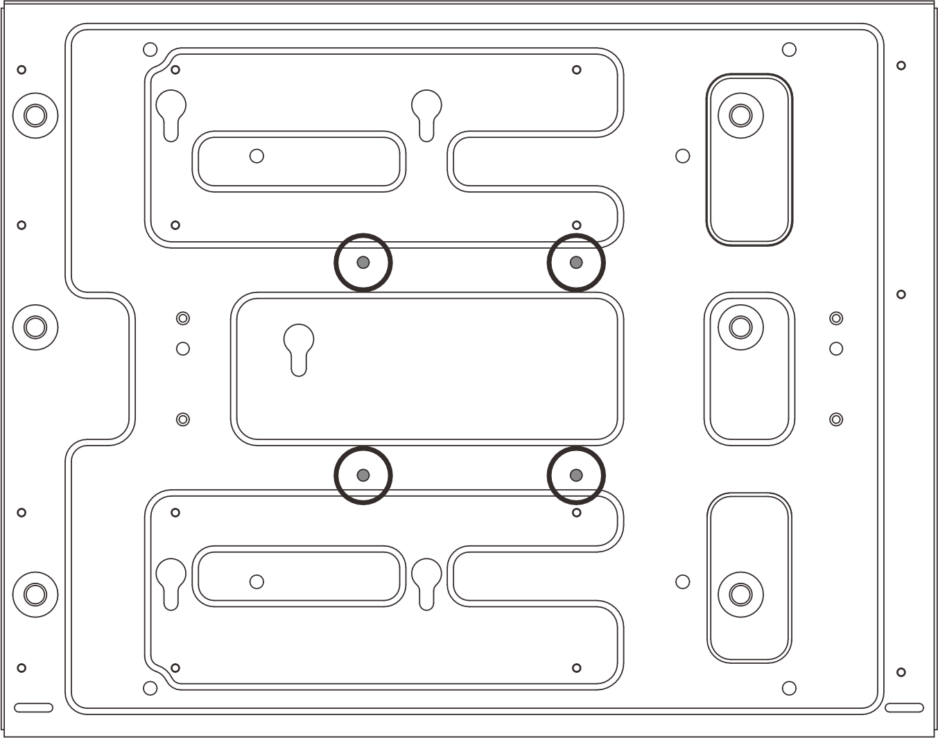 Figure 7. Locations of M6 screws
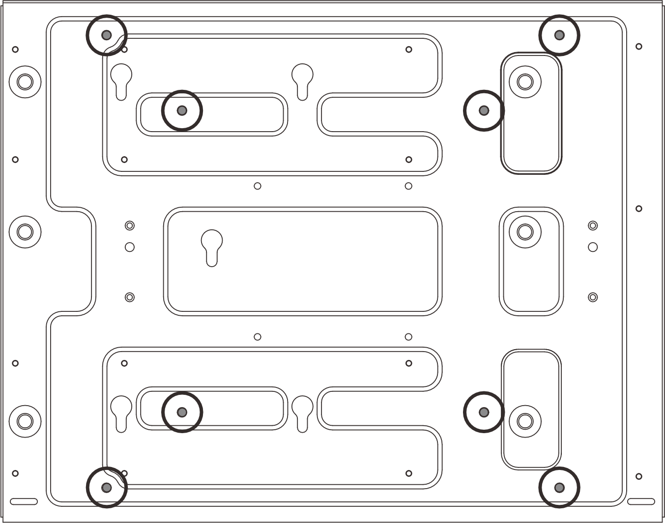
Demo video
Give documentation feedback