Install a node to the wall or the ceiling
Follow instructions in this section to install a node to the wall or the ceiling.
About this task
Read Installation Guidelines and Safety inspection checklist to ensure that you work safely.
Power off the server and peripheral devices and disconnect the power cords and all external cables. See Power off the server.
Reserve 500 mm of clearance in front of the node for installation/removal procedure.
For safe installation, the wall to mount the node must be able to support 5 times of the weight. If not, the surface must be reinforced to meet this standard.
Maximal weight 5 times of maximal weight SE100 node with node sleeve 7.3 KG (16 lbs) 36.5 KG (80 lbs) SE100 node and expansion kit with node sleeve 7.9 KG (17.4 lbs) 39.5 KG (87 lbs) Avoid existing in-wall utilities, for example, plumbing, natural gas, or electrical input.
- If the node sleeve is already installed on the wall, start from Install the node into the node sleeve
- Depending on the model, your server might look slightly different from the illustration.
Install the node sleeve assembly to the wall
Procedure
- The wall mount configuration requires four M4 screws and eight M6 screws. Prepare screws and related parts for this task.NoteThe appropriate length of the screw base should be assessed by qualified professionals.
Table 1. Max screw size for the inner four M4 screws 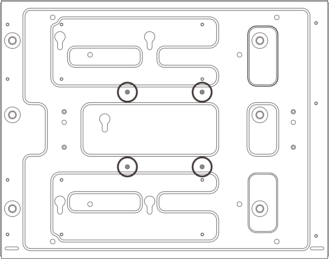
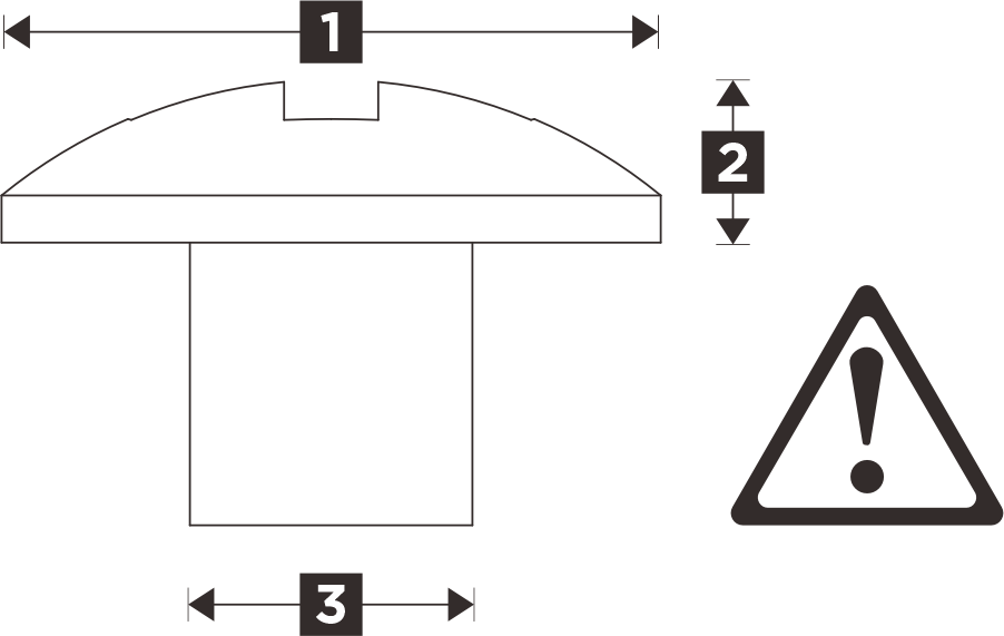
1 8.5-10.5 mm (0.334-0.413 inch) 2 3-3.4 mm (0.118-0.133 inch) 3 M4 (#7-19T) Table 2. Max screw size for the outer eight M6 screws 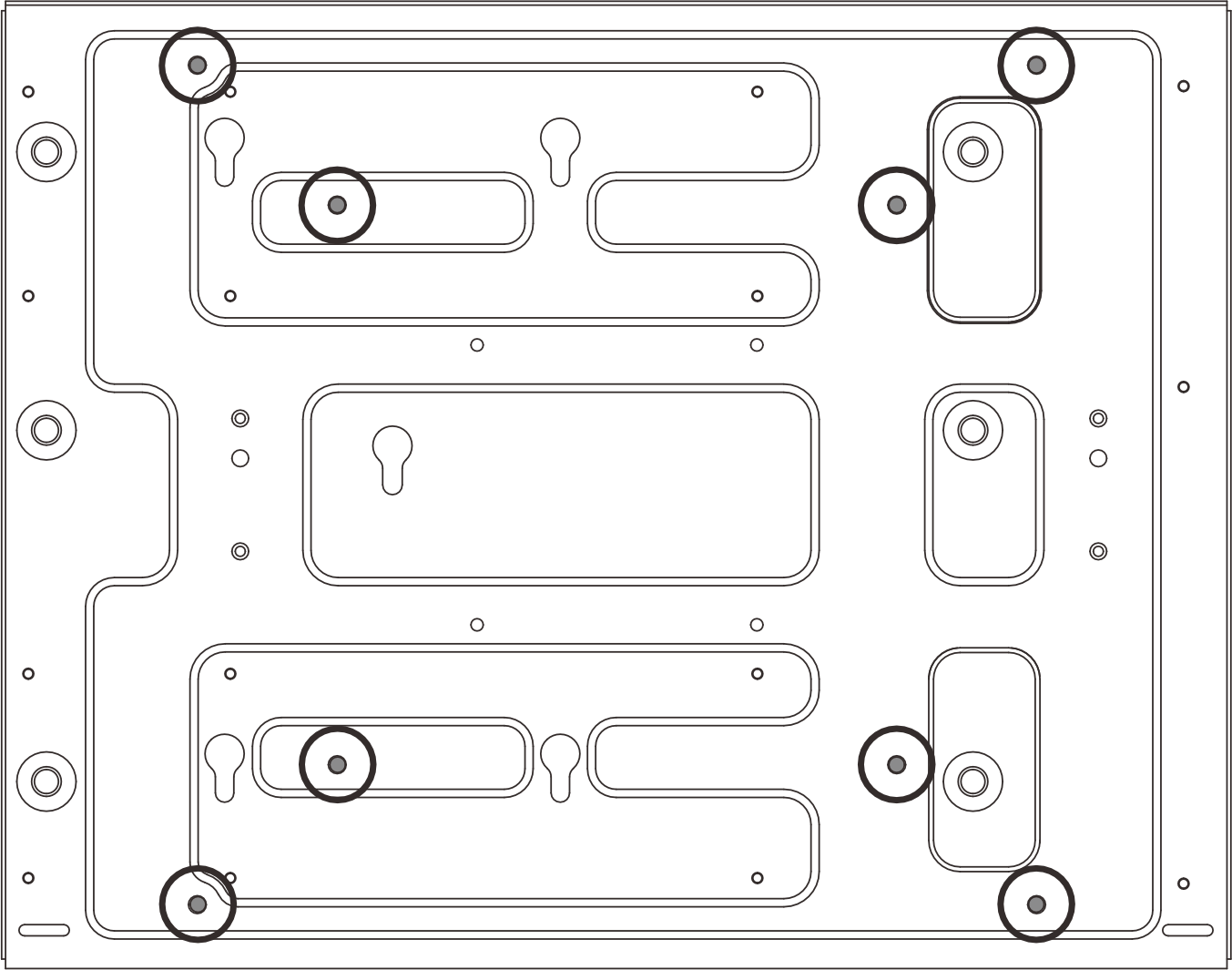
1 12.5-14.5 mm (0.492-0.570 inch) 2 3-3.4 mm (0.118-0.133 inch) 3 M6 (#14-14T) - Remove the node sleeve from the mount plate.
- Remove the eleven screws that secure the node sleeve.Figure 1. Removing the node sleeve with expansion kit
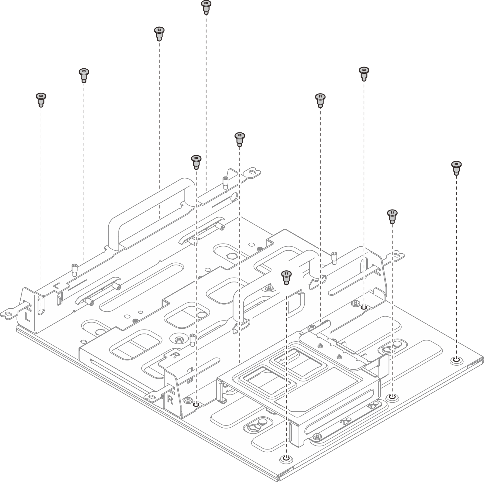 Figure 2. Removing the node sleeve without expansion kit
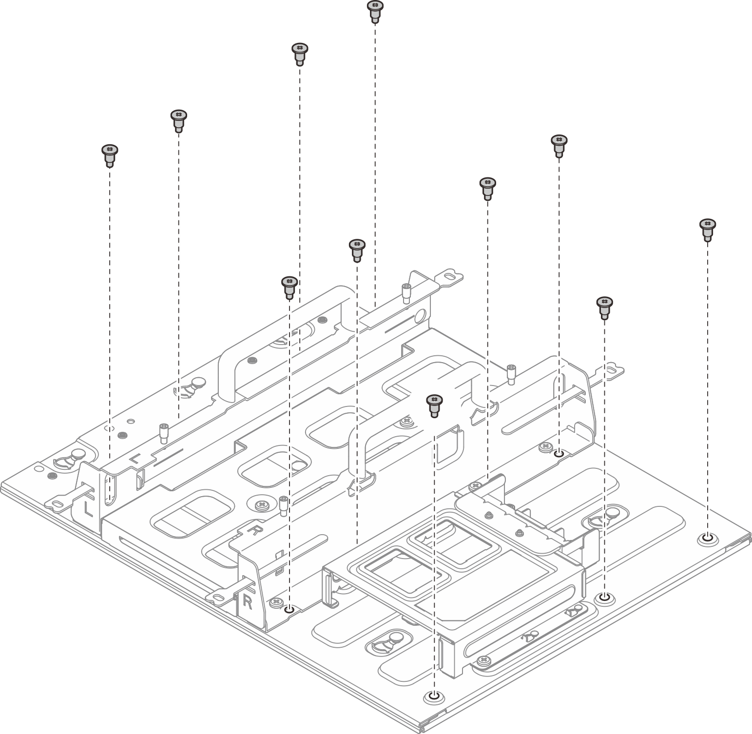
- Slide the node sleeve until the guide pins on the mount plate are seated in the large opening of the keyhole; then, remove the node sleeve from the mount plate.Figure 3. Removing the node sleeve
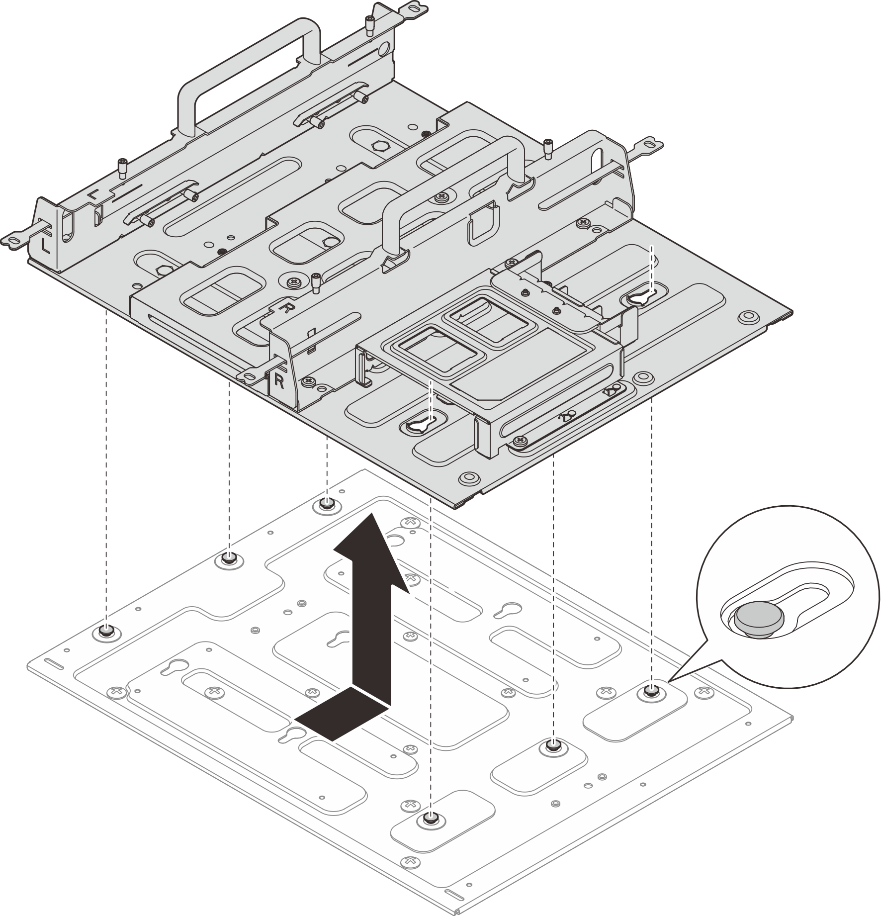
- Remove the eleven screws that secure the node sleeve.
- (Optional) To mount the mount plate on a flat wall with no screw holes, drill twelve screw holes on the wall if necessary.
- Press the mount plate against the mounting location.
- Mark the locations of screw holes with a pencil.
- Drill twelve screw holes as marked.
Figure 4. Drilling screw holes Figure 5. Distance between screw holes
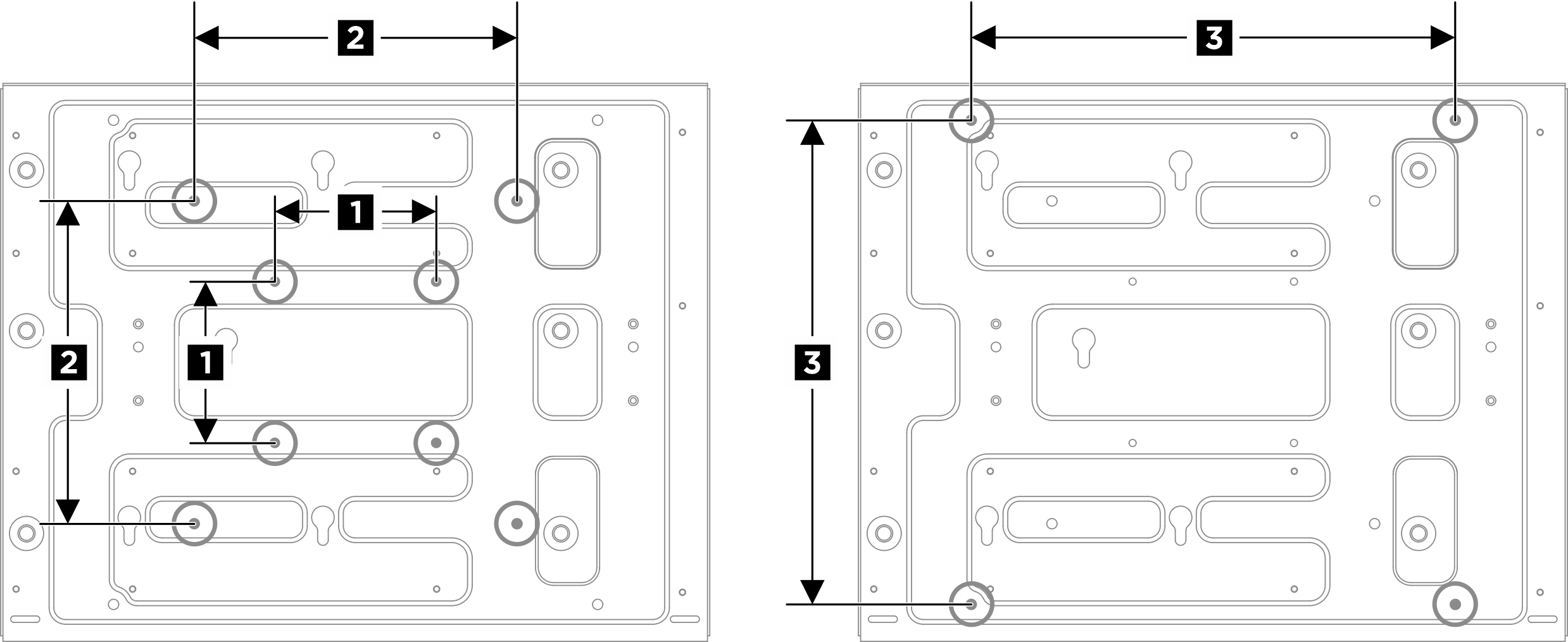
1 100 mm 3 300 mm 2 200 mm - Secure the mount plate to the wall with four M4 screws and eight M6 screws.Figure 6. Installing the mount plate
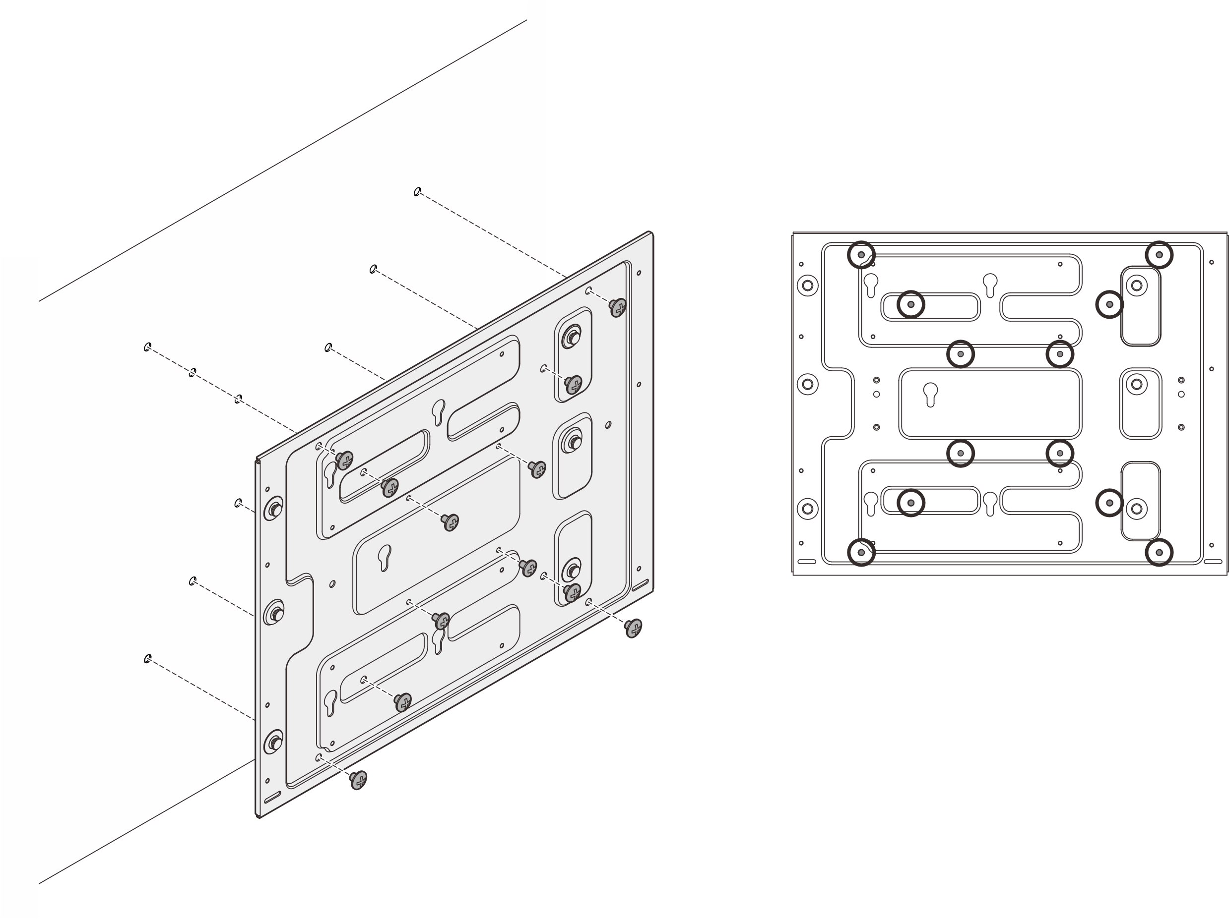 Figure 7. Locations of M4 screwsFigure 8. Locations of M6 screws
 - Install the node sleeve to the mount plate.
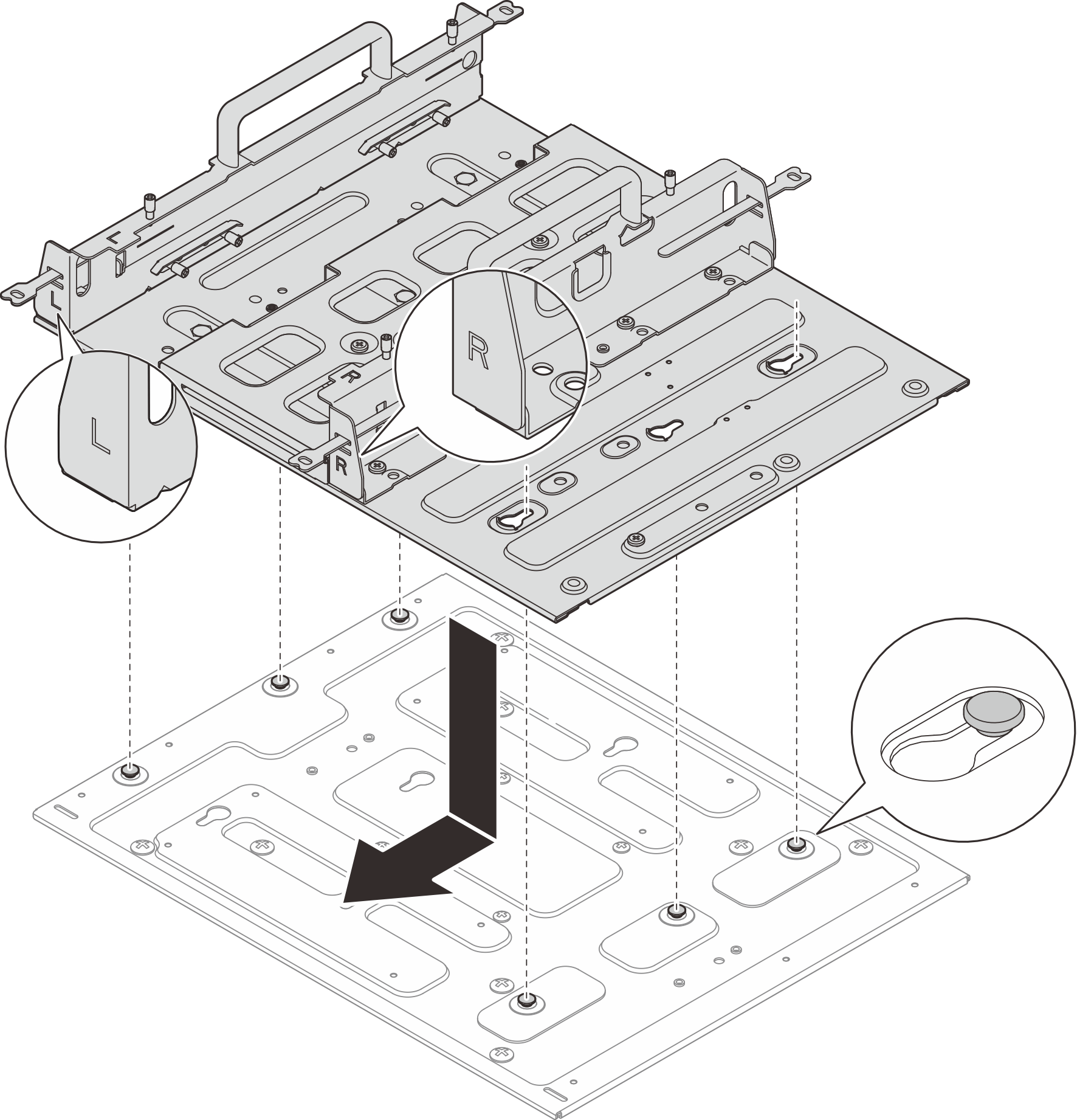
- Push the node sleeve onto the mount plate; then, slide the node sleeve until the guide pins are seated in the small opening of keyholes.NoteThere are “L” and “R” logos marked on the front of node sleeve holder which represents the left hand and right hand of the user. Make sure to install the node sleeve with correct orientation shown in the illustration.Figure 9. Installing the node sleeve
- Secure the node sleeve with eleven screws.Figure 10. Installing the node sleeve with expansion kit
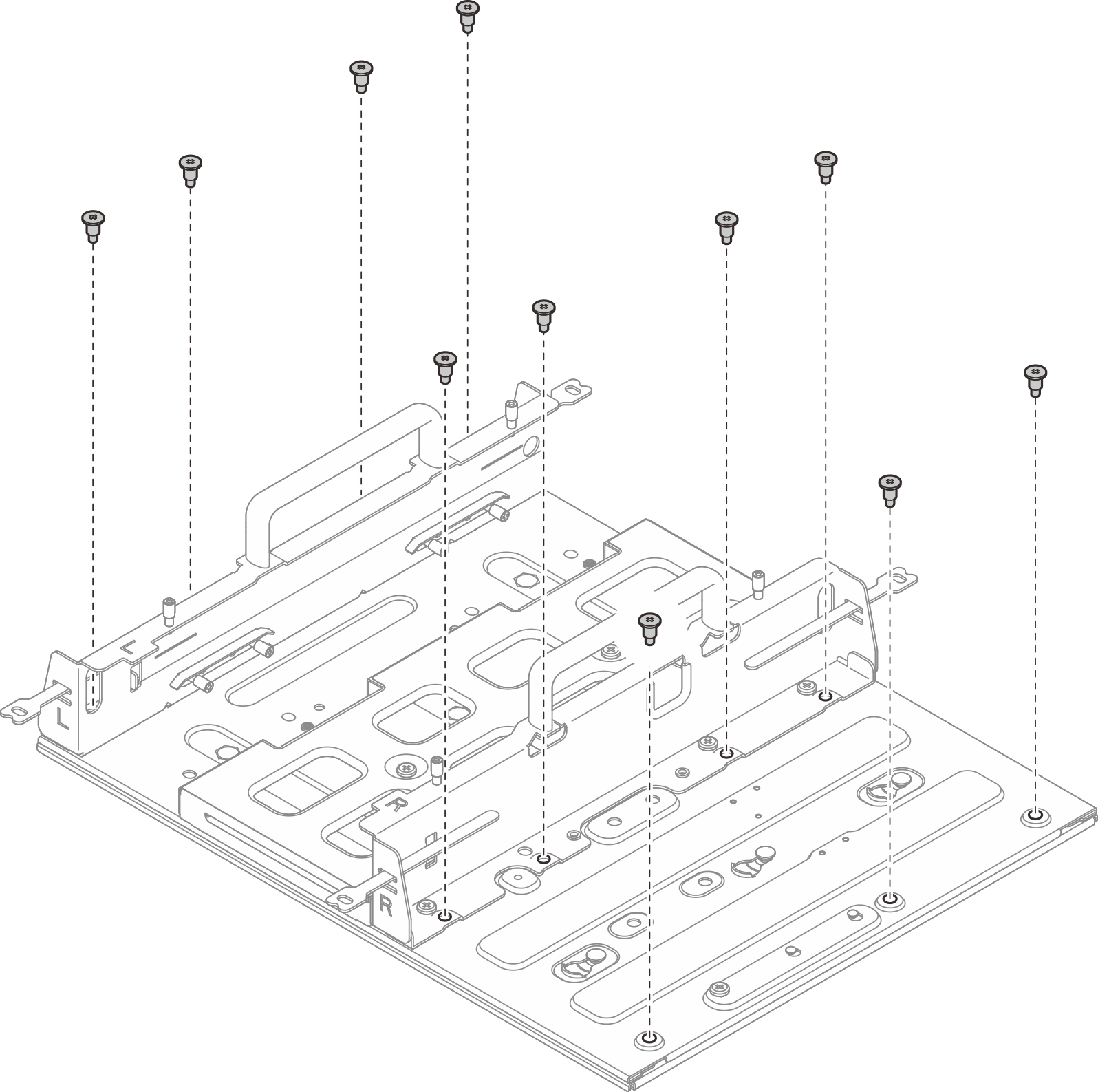 Figure 11. Installing the node sleeve without expansion kit
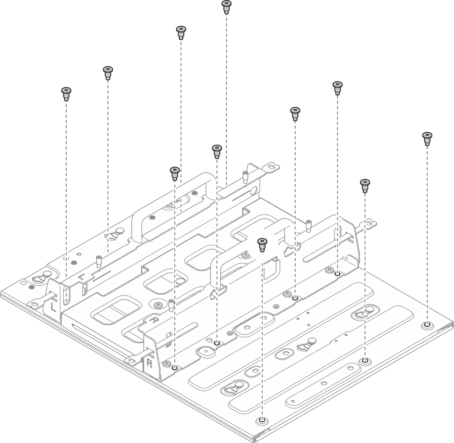
- Push the node sleeve onto the mount plate; then, slide the node sleeve until the guide pins are seated in the small opening of keyholes.
Install the node into the node sleeve
Procedure
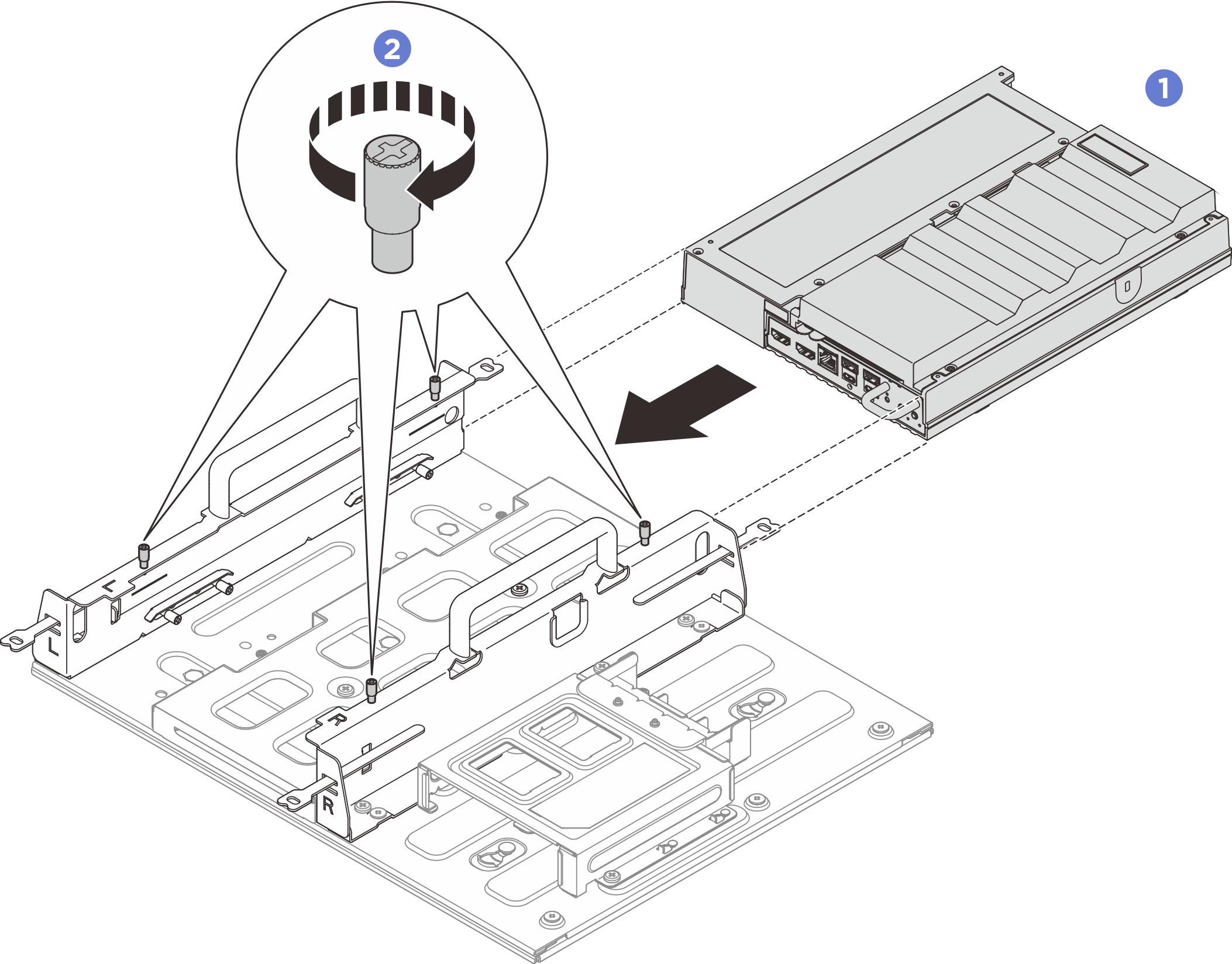
 Align the node with the node sleeve; then, insert and slide the node into the node sleeve until it stops.
 Tighten the four thumbscrews on the side of the node sleeve.
Install the power adapter and power adapter cage. See Install a power adapter (wall/ceiling/DIN rail mount).
If you are instructed to return the component or optional device, follow all packaging instructions, and use any packaging materials for shipping that are supplied to you.
Demo video