Install a power adapter (wall/ceiling/DIN rail mount)
Follow instructions in this section to install power adapter(s).
About this task
- S002
 CAUTIONThe power-control button on the device and the power switch on the power supply do not turn off the electrical current supplied to the device. The device also might have more than one power cord. To remove all electrical current from the device, ensure that all power cords are disconnected from the power source.
 - S035
 CAUTION
Never remove the cover on a power supply or any part that has this label attached. Hazardous voltage, current, and energy levels are present inside any component that has this label attached. There are no serviceable parts inside these components. If you suspect a problem with one of these parts, contact a service technician.
Read Installation Guidelines and Safety inspection checklist to ensure that you work safely.
Touch the static-protective package that contains the component to any unpainted metal surface on the server; then, remove it from the package and place it on a static-protective surface.
Power adapters to the node must be of the same brand, power rating, wattage or efficiency level.
| ThinkEdge 140W 230V/115V External Power Supply | ||
|---|---|---|
Information published | Value and precision | Unit |
Manufacturer’s name | Lenovo | - |
Model identifier | Adapter | - |
Input voltage | 100-240 | V |
Input AC frequency | 50-60 | Hz |
Output voltage | 28.0 | V |
Output current | 5.0 | A |
Output power | 140.0 | W |
Average active efficiency |
| % |
Efficiency at low load (10 %) |
| % |
No-load power consumption |
| W |
- If applicable, install the power adapter bracket.
 Align the power adapter bracket with the guide pins on node sleeve, and then slide the power adapter bracket until the guide pins are seated on the small opening of the keyholes.
 Tighten two screws to secure the power adapter bracket.Figure 1. Installing the power adapter bracket
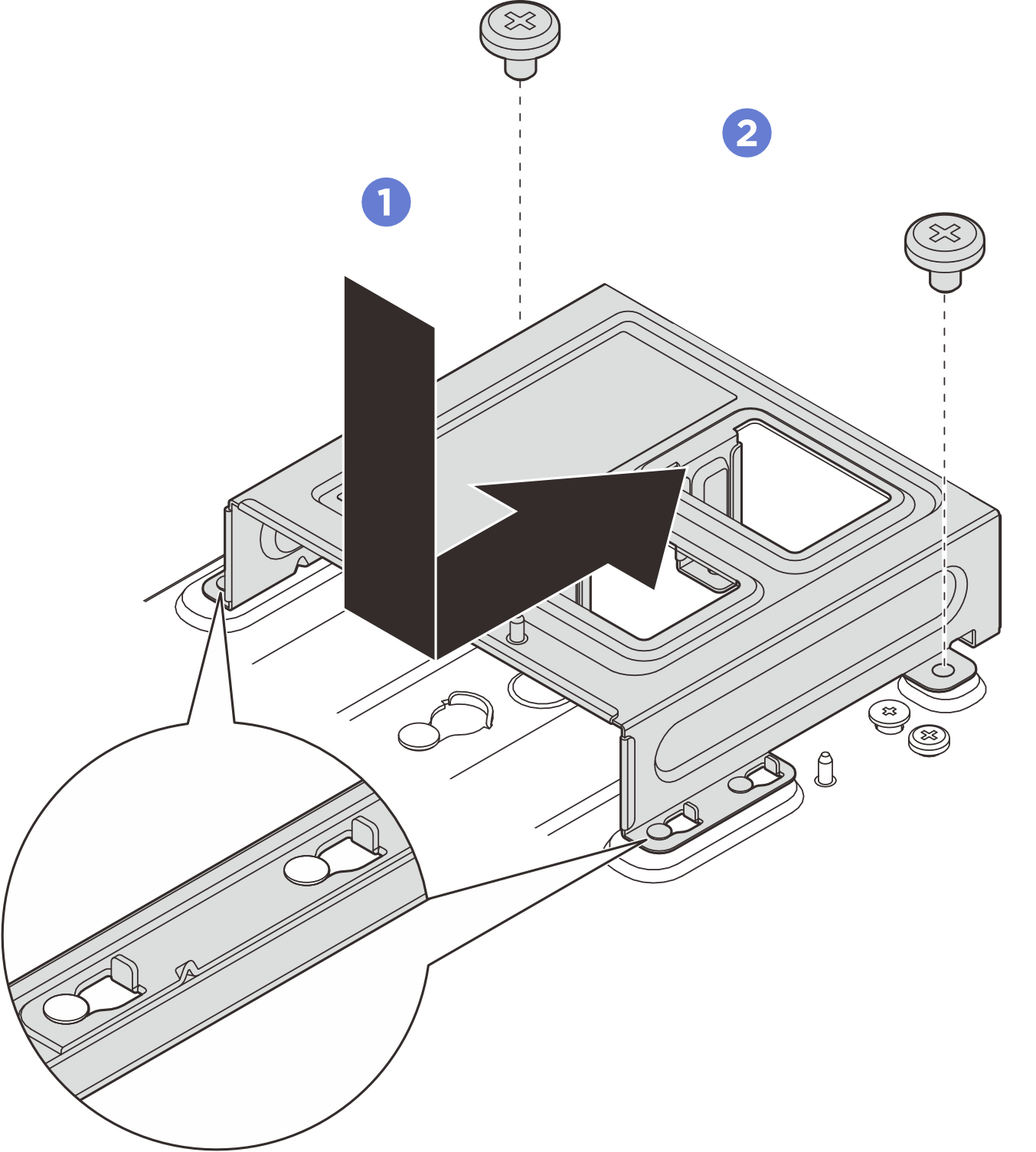
- Install the power adapters.NoteUse the information below to locate the power adapter slot numbering. If there is only one power adapter to be installed, install the power adapter to slot 1.Figure 2. Power adapter slot numbering
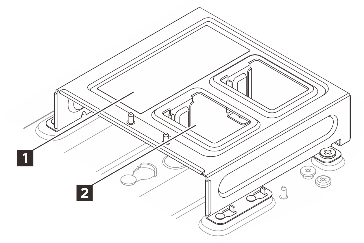
1 Power adapter slot 1 1 Power adapter slot 2  Align the power adapters with the power adapter cage; then, slide the power adapters in place.
 Align the two screw holes on the tab with the power adapter bracket; then fully tighten the two thumbscrews to secure the tab.
Figure 3. Installing the power adapter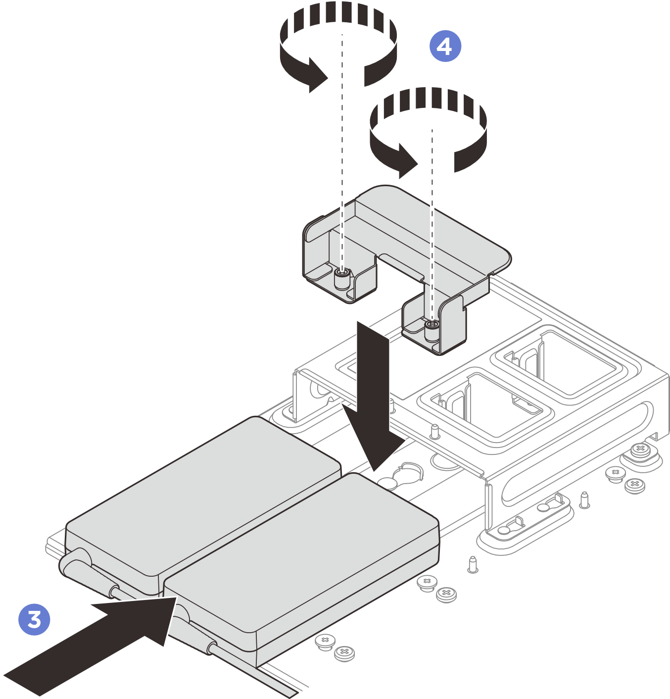
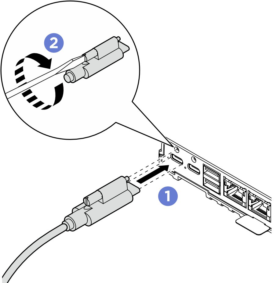
- Connect the power cable to the node.
- Align the screw holes and install the power cable to the node.
- Tighten the screw and make sure the power cable is securely locked.NoteMake sure to connect the power adapter in slot 1 to power connector 1, and connect power adapter in slot 2 to power connector 2.Figure 4. Connecting the power cable
Demo video