System-board LEDs
The following illustrations show the light-emitting diodes (LEDs) on the system board.
| Top side | Bottom side |
Figure 1. System board LEDs on top side 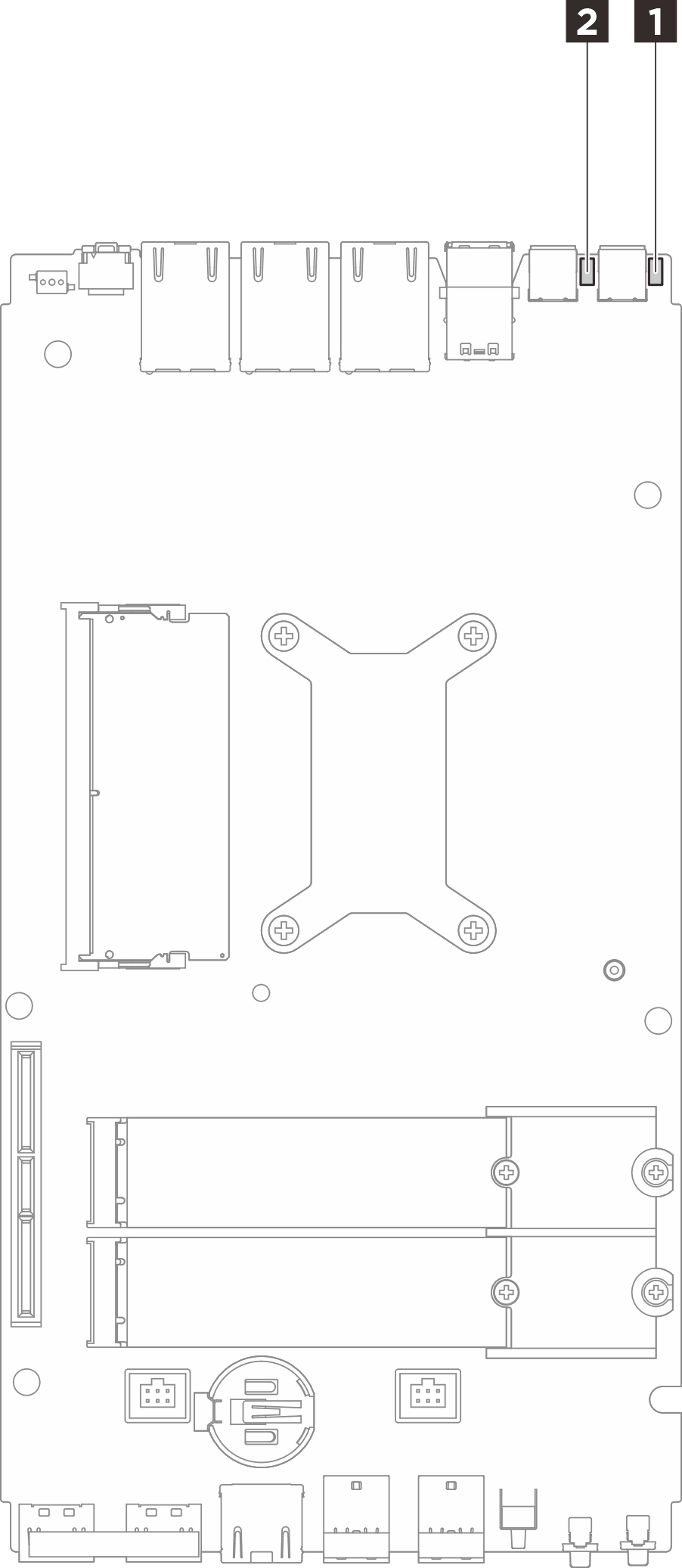 | Figure 2. System board LEDs on bottom side 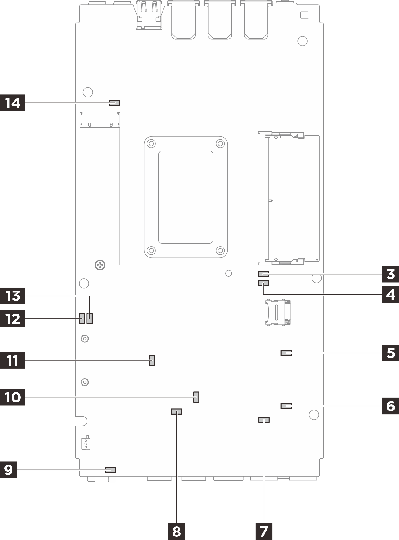 |
| LED | Description and actions |
|---|---|
1 Adapter 1 status LED 2 Adapter 2 status LED | The states of the adapter LED are as follows:
|
3 DIMM 1 error LED 4 DIMM 2 error LED | LED on: an error has occurred to the DIMM the LED represents. |
5 M.2 slot 2 status LED 6 M.2 slot 3 status LED 14 M.2 slot 1 status LED | The states of the M.2 LED are as follows:
|
7 Fan 1 error LED 8 Fan 2 error LED | LED on: an error has occurred to the fan the LED represents. |
| 9 System error LED (yellow) | LED on: an error has occurred. Complete the following steps:
|
| 10 XCC status LED | The states of the XCC status LED are as follows:
|
| 11 XCC heartbeat LED (green) | This LED indicates the XCC heartbeat and boot process:
|
| 12 FPGA power status LED (green) | The FPGA power LED helps to identify different FPGA errors.
|
| 13 FPGA heartbeat LED (green) | This LED indicates power-on and power-off sequencing.
|