System-board switches
The following illustrations show the location of the switches, jumpers, and buttons on the server.
Note
If there is a clear protective sticker on the top of the switch blocks, you must remove and discard it to access the switches.
Important
Before you change any switch settings or move any jumpers, turn off the server; then, disconnect all power cords and external cables. Review the following information:
- Any system-board switch or jumper block that is not shown in the illustrations in this document are reserved.
Figure 1. System-board switches (System board bottom side)
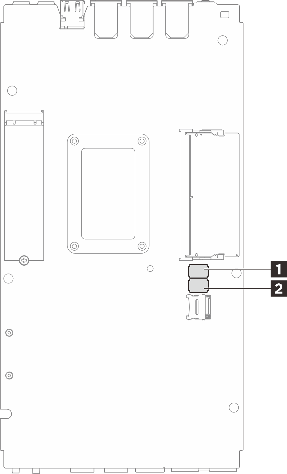
The following table describes the functions of the switches on the bottom side of the system board.| Switches block | Switch number | Switch name | Usage description | |
|---|---|---|---|---|
| On | Off | |||
| 1 SW1 | 1 | XClarity Controller boot backup | The node boots by using a backup of the XCC firmware | Normal (default) |
| 2 | CMOS clear | Clears the real-time clock (RTC) registry | Normal (default) | |
| 3 | Password override | Overrides the power-on password | Normal (default) | |
| 4 | (Reserved) | (Reserved) | Normal (default) | |
| 5 | Serial function selection | Accesses XCC via the serial console connector | Normal (default) | |
| 6 | Machine Engine (ME) recovery override | ME boots to recovery | Normal (default) | |
| 7 | (Reserved) | (Reserved) | Normal (default) | |
| 8 | (Reserved) | (Reserved) | Normal (default) | |
| 2 SW2 | 1 | Machine Engine (ME) firmware security override | Enables ME update mode | Normal (default) |
| 2 | XCC force update | Enables XCC force update | Normal (default) | |
| 3 | FPGA power permission override | Ignores Power Permission and allows system to power-on | Normal (default) | |
| 4 | Force XCC reset | Forces XCC to reset | Normal (default) | |
| 5 | Force XCC CPU reset | Forces XCC and CPU to reset | Normal (default) | |
| 6 | Force DnX reload | Enter DnX mode | Normal (default) | |
| 7 | Force FPGA reset | Forces FPGA to reset | Normal (default) | |
| 8 | (Reserved) | (Reserved) | Normal (default) | |
Give documentation feedback