Rear view
This section contains information about the LEDs and connectors on the rear of the server.
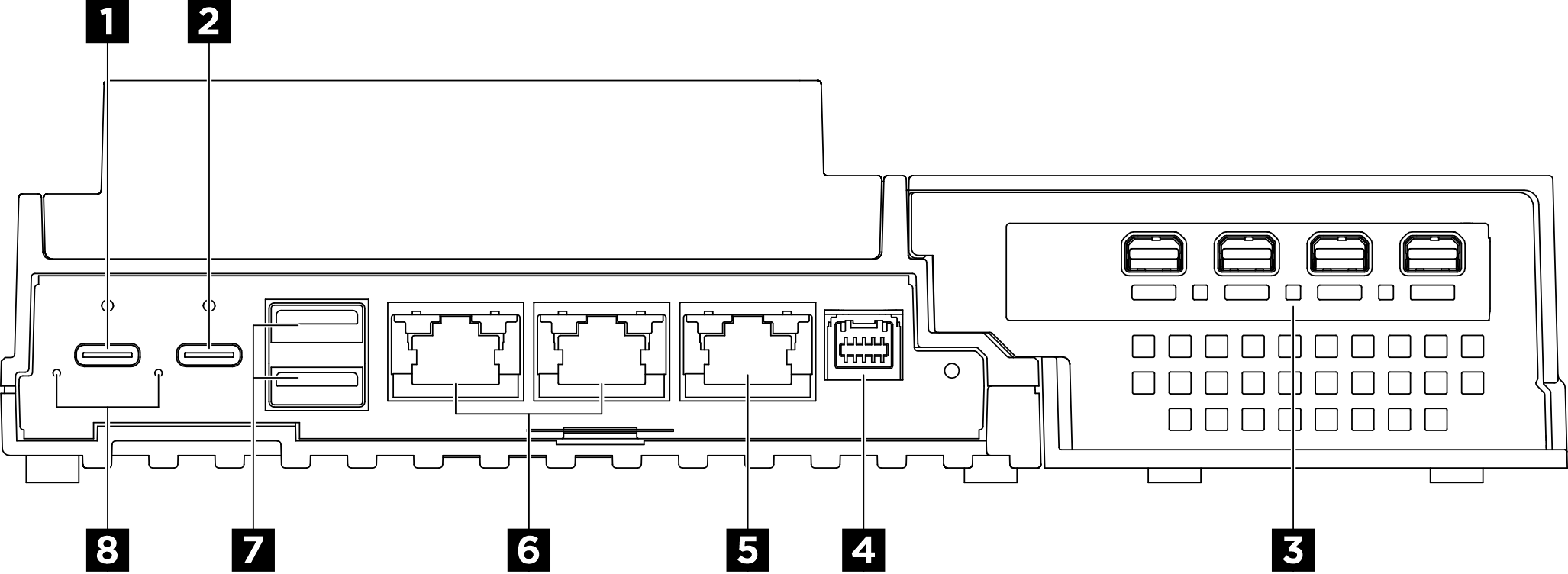
| 1 USB Type-C power connector 1 | 2 USB Type-C power connector 2 with USB 2.0 Lenovo XClarity Controller management |
| 3 Expansion kit | 4 Fan control board connector |
| 5 XCC system management port (10/100/1000 Mbps RJ-45) | 6 1GbE RJ-45 connectors |
| 7 USB 3.2 Gen2 (10 Gbps) Type-A connectors | 8 Power input LEDs (green/yellow) |
1 2 USB Type-C power connectors
Connection to Lenovo XClarity Controller is primarily intended for users with a mobile device running the Lenovo XClarity Controller mobile application. When a mobile device is connected to this USB port, an Ethernet over USB connection is established between the mobile application running on the device and the Lenovo XClarity Controller.
BMC only mode
In this mode, the USB port is always solely connected to Lenovo XClarity Controller.
3 Expansion kit
The PCIe adapter is installed in the expansion kit. The rear connectors vary by the type of PCIe adapter.
To install a PCIe adapter into the expansion kit, see Install the PCIe adapter for more information.
4 Fan control board connector
Connect a fan control board power cable to this connector for the server installed in the enclosure. See Internal cable routing of SE100 Enclosure for more information.
5 XCC system management port (10/100/1000 Mbps RJ-45)
The server has a 10/100/1000 Mbps RJ-45 connector dedicated to Lenovo XClarity Controller (XCC) functions. Through the system management port, you can access the Lenovo XClarity Controller directly by connecting your laptop to the management port using an Ethernet cable. Make sure that you modify the IP settings on the laptop so that it is on the same network as the server default settings. A dedicated management network provides additional security by physically separating the management network traffic from the production network.
6 1GbE RJ-45 connectors
Connect an Ethernet cable to either of these connectors for LAN connection. See XCC system management port (10/100/1000 Mbps RJ-45) and LAN port LEDs for more information.
7 USB 3.2 Gen2 (10 Gbps) Type-A connectors
Connect a USB device, such as a mouse, keyboard, or other devices, to either of these connectors.
8 Power input LEDs (green/yellow)
| LED | Status | Description |
| Power input LED | On (green) | The server is connected to the power adapter and working normally. |
| On (yellow) | The server is connected to the power adapter but can not be powered on since the power capability is unable to support the system requirement. | |
| Off | The power adapter is disconnected or a power problem occurs. |
Rear I/O fillers
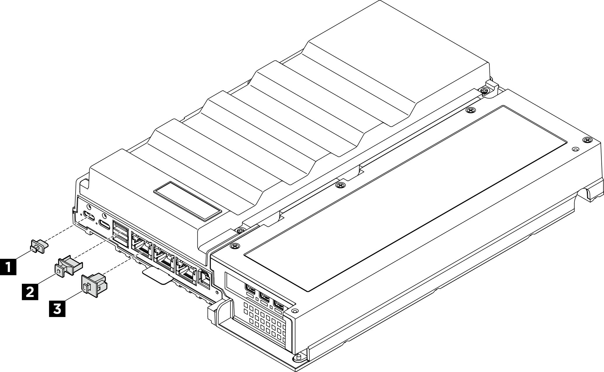
| 1 USB Type-C filler (x2) | 2 USB Type-A filler (x2) |
| 3 RJ-45 filler (x3) |