Front view
This section contains information about the controls, LEDs, and connectors on the front of the server.
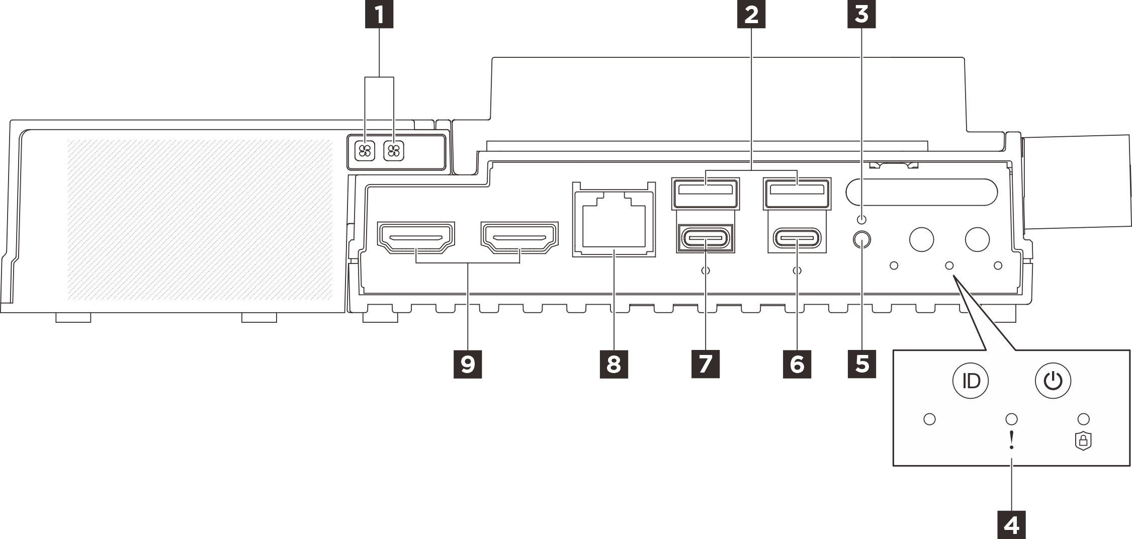
| 1 Fan error LED of Ethernet adapter expansion kit (Amber) | 2 USB 3.2 Gen2 (10 Gbps) Type-A connectors (USB port 1 and port 2) |
| 3 | 4 |
| 5 UART switch button | 6 USB 3.2 Gen 2 (10 Gbps) Type-C connector with display support (USB port 4) |
| 7 USB 3.2 Gen 2 (10 Gbps) Type-C connector with display support (USB port 3) | 8 RJ-45 RS-232 serial console connector for OS/BIOS or XCC |
| 9 HDMI 2.0 connectors |
1 Fan error LED of Ethernet adapter expansion kit (Amber)
When a fan error LED on the Ethernet adapter expansion kit is lit, it indicates that the corresponding system fan is operating slowly or has failed.
2 USB 3.2 Gen2 (10 Gbps) Type-A connectors (USB port 1 and port 2)
Connect a USB device, such as a mouse, keyboard, or other devices, to either of these connectors.
6 USB 3.2 Gen 2 (10 Gbps) Type-C connector with display support (USB port 4)
The maximum video resolution is 4K at 60 Hz.
The connector supports up to 15 watts of power (5V/3A).
7 USB 3.2 Gen 2 (10 Gbps) Type-C connector with display support (USB port 3)
Connect a USB device, such as a mouse, keyboard, monitor, or other devices, to this connector. Configure the UEFI setting through this port as a priority.
It is recommended to connect a monitor to USB port 3 (with display support) while powering on the system. The output of error messages during system booting is from USB port 3. After entering the OS, if the monitor connecting to USB port 3 becomes blank, connect the monitor to another display port. See Monitor and video problems for more information.
The maximum video resolution is 1920 x 1200 at 60 Hz.
The connector can support up to 15 watts of power (5V/3A).
8 RJ-45 RS-232 serial console connector for OS/BIOS or XCC
Connect an external RJ-45 serial COMM console cable to this RS-232 serial console with RJ-45 connector.
9 HDMI 2.0 connectors
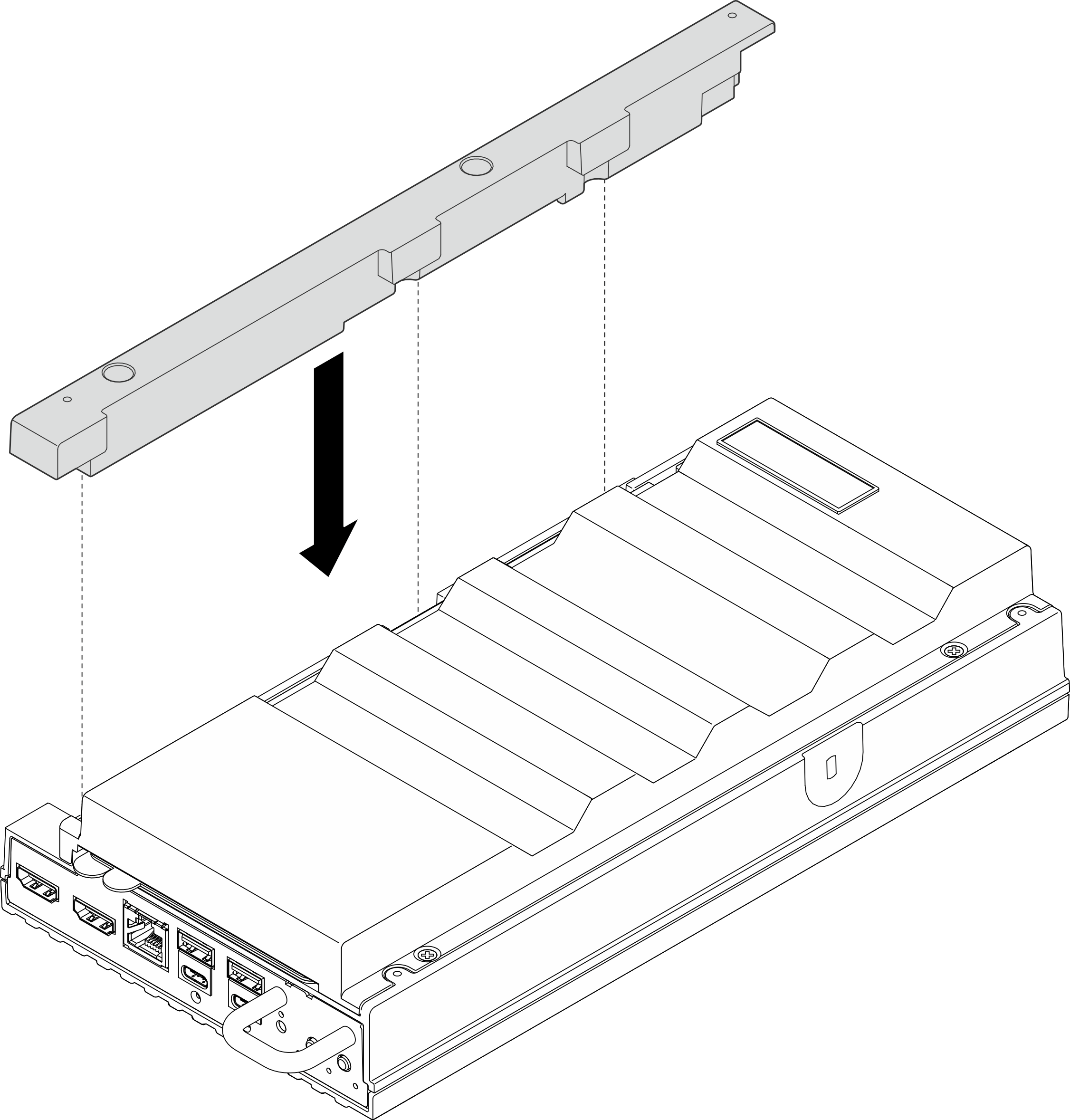
Expansion filler
Front I/O fillers
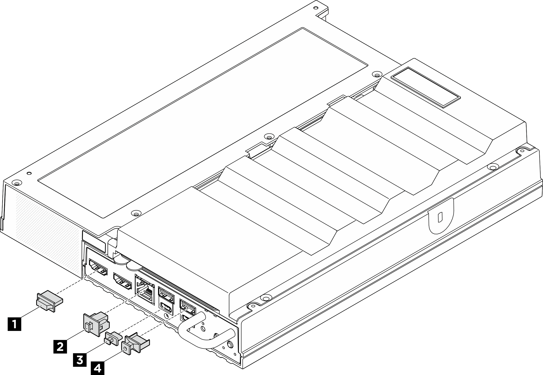
| 1 HDMI connector filler (x2) | 2 RJ-45 filler (x1) |
| 3 USB Type-C filler (x2) | 4 USB Type-A filler (x2) |