PCIe riser card cable routing
Follow the instructions in this section to learn how to do cable routing for the PCIe riser cards.
See the corresponding section to complete the PCIe riser card cable routing:
PCIe riser 1 riser card cable routing
This section provides cable routing instructions for the following cables:
| Cable | Color | From: PCIe riser 1 | To: system board |
|---|---|---|---|
| Riser 1 signal cable, 280mm/320mm | Blue | MCIO3, MCIO4 | PCIe 8, PCIe 9 |
| Riser 1 signal cable, 375mm/360mm | Silver | MCIO1, MCIO2 | PCIe 6, PCIe 7 |
Complete the following procedure to route the cables properly.
Procedure
- Connect the signal cables to the system board and route the cables.
- Connect the blue signal cable to PCIe 8 and PCIe 9 connectors on the system board.
- Connect the silver signal cable to PCIe 6 and PCIe 7 connectors on the system board.
- Route the blue signal cable along the intrusion switch as shown.
- Route the silver signal cable through the cable wall. Press the cable down toward the system board to avoid interfering with the retaining clips of memory module slots.
Figure 1. PCIe riser 1 cable routing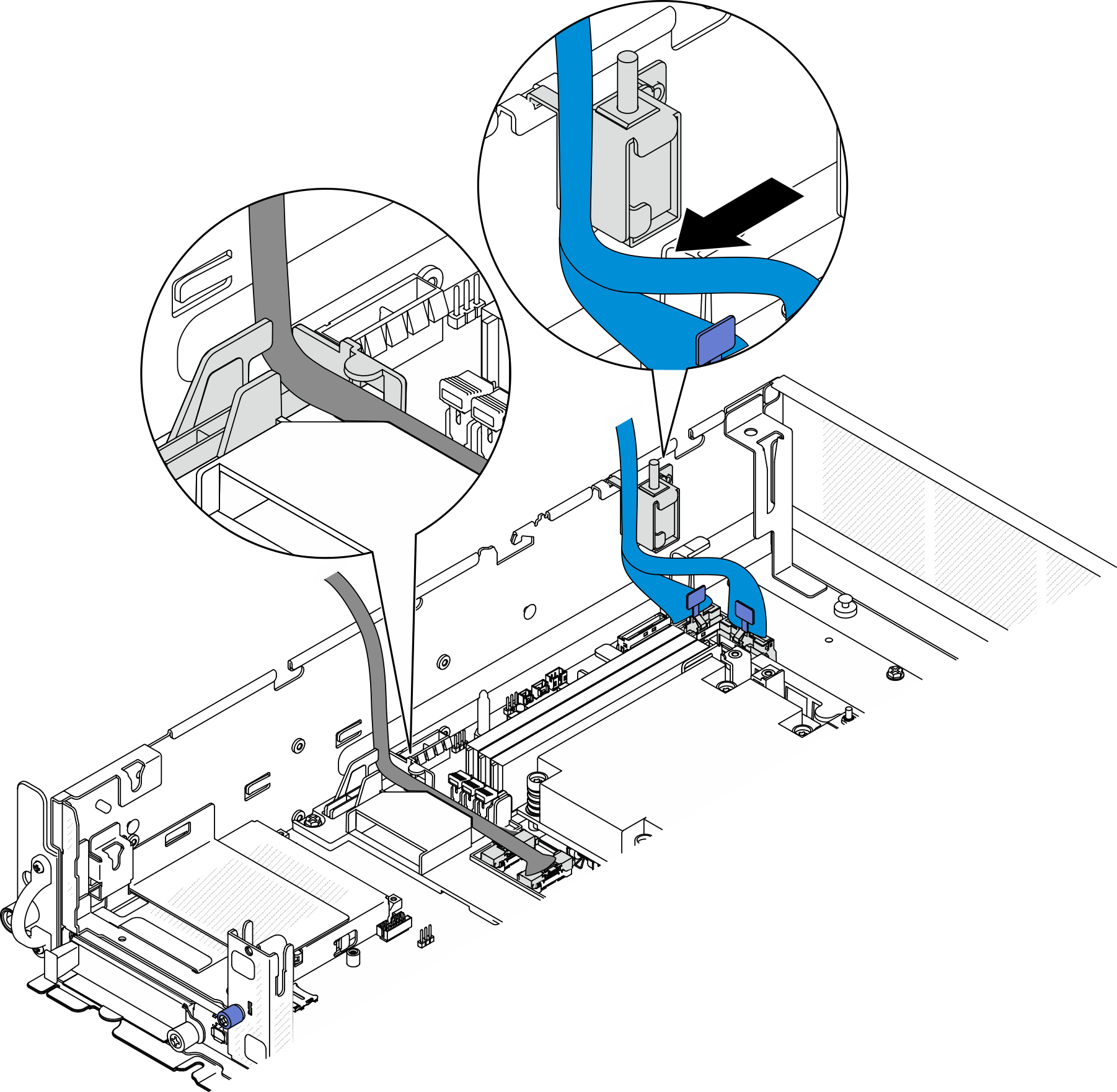
PCIe riser 2 riser card cable routing
This section provides cable routing instructions for the following cables:
| Cable | Color | From: PCIe riser 2 | To: system board |
|---|---|---|---|
| Riser 2 signal cable, 450mm/450mm* | Blue | MCIO3, MCIO4 | PCIe 2, PCIe 3 |
| Riser 2 signal cable, 400mm/385mm | Silver | MCIO1, MCIO2 | PCIe 4, PCIe 5 |
*The blue signal cable is not supported in the following configurations:
- Front SATA drive backplane and internal NVMe drive backplane connect to the system board
- Front NVMe drive backplane and internal NVMe drive backplane connect to the system board
Complete the following procedure to route the cables properly.
Procedure
- Connect the power and signal cables to the system board and route the cablesFigure 2. PCIe riser 2 cable routing
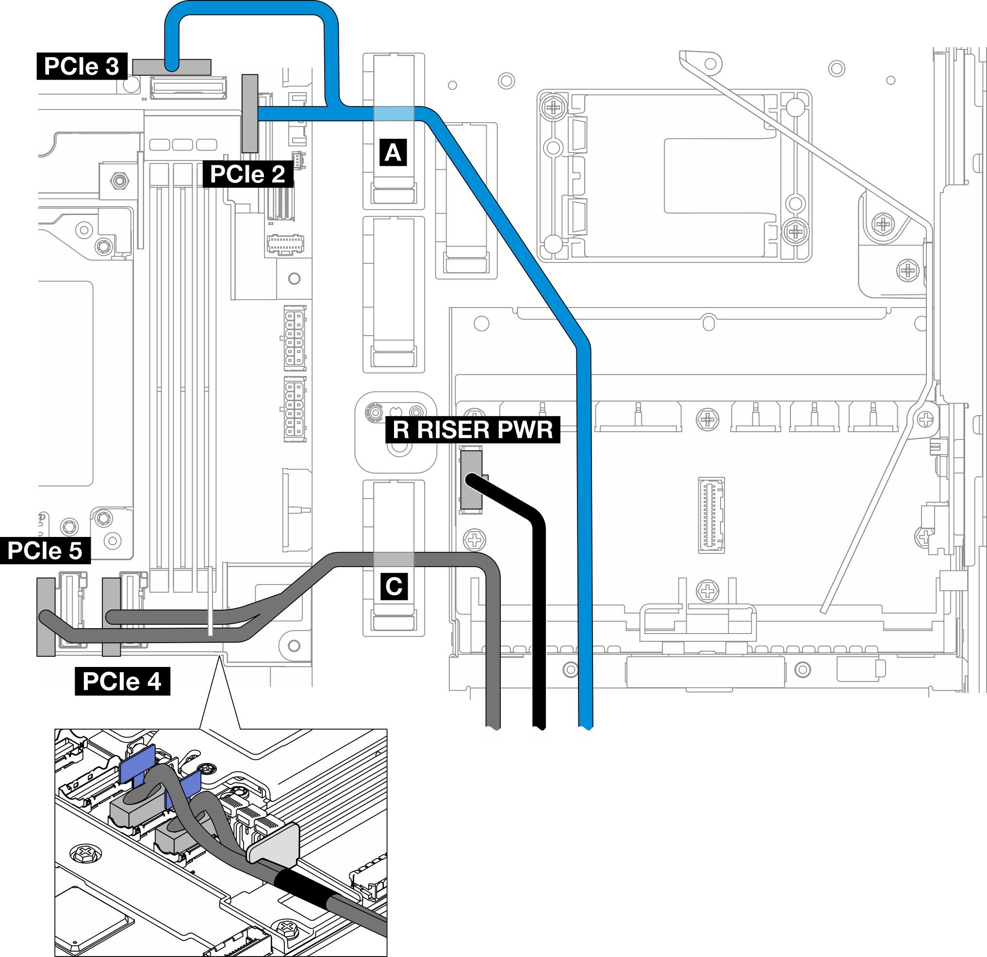
- If applicable, connect the blue signal cable to PCIe 2 and PCIe 3 connectors on the system board.
- Connect the power cable to Riser 2 power connector (R RISER PWR) on the power distribution board.
- Connect the silver signal cable to PCIe 4 and PCIe 5 connectors on the system board.
- If applicable, secure the blue signal cable in cable clip A.
- Route the silver signal cable through the cable wall; then, secure the cable in cable clip C. Press the cable down toward the system board to avoid interfering with the retaining clips of memory module slots.
Give documentation feedback