Install the PCIe riser card
Follow the instructions in this section to install the PCIe riser card.
About this task
Read Installation Guidelines and Safety inspection checklist to ensure that you work safely.
Power off the server and peripheral devices and disconnect the power cords and all external cables. See Power off the server.
Touch the static-protective package that contains the component to any unpainted metal surface on the server; then, remove it from the package and place it on a static-protective surface.
See the section corresponding to the PCIe riser card to be installed.
Install the PCIe riser card to PCIe riser 1
Procedure
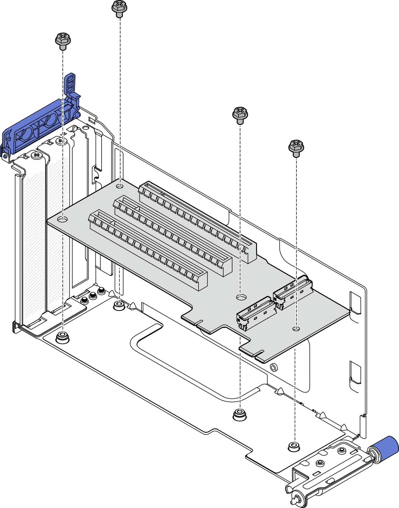
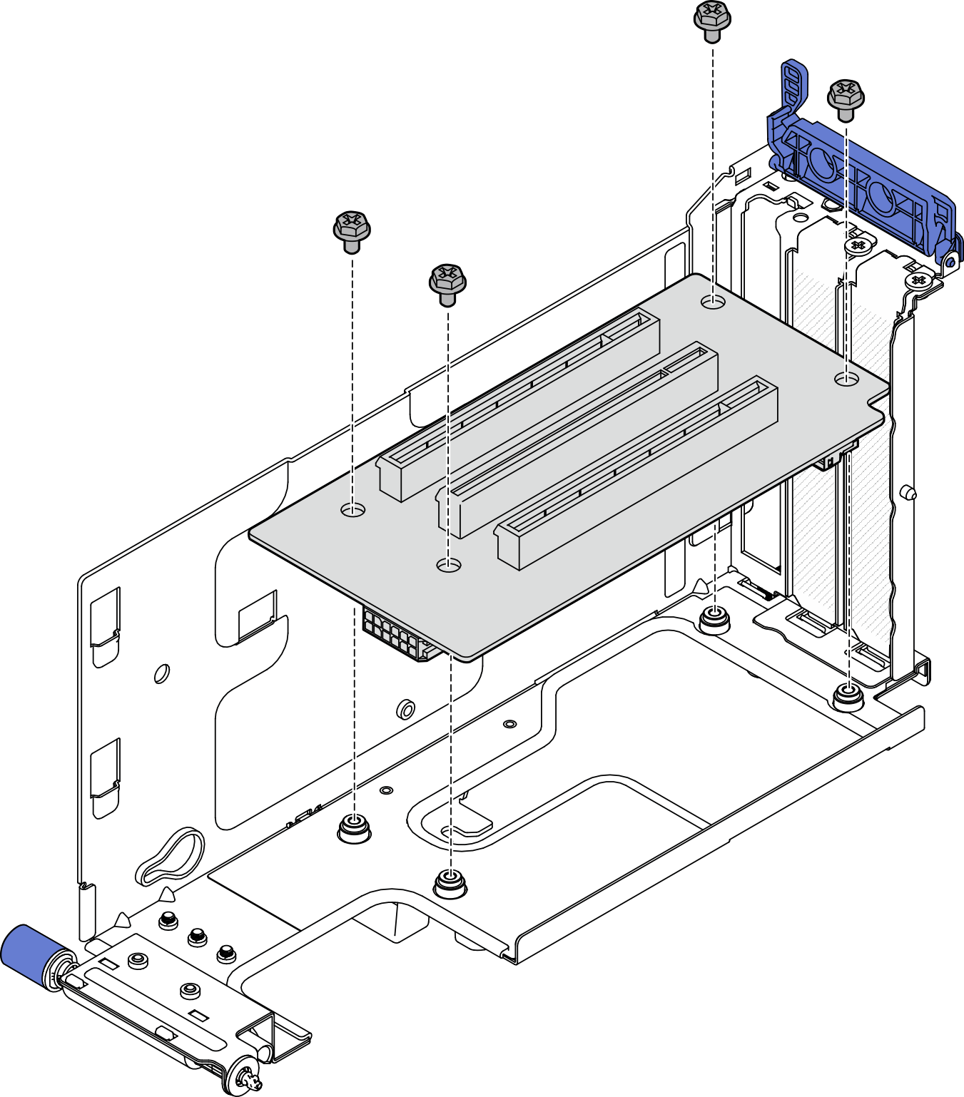
- Align the holes on the riser card with the guide pins on the riser cage; then, fasten four screws to secure the riser card.Figure 1. Installing the riser card
- Connect the blue signal cable to PCIe riser 1.
 Connect the cable to MCIO3 connector.
 Connect the cable to MCIO4 connector.
 Route the cable as shown.
Figure 2. PCIe riser 1 cable routing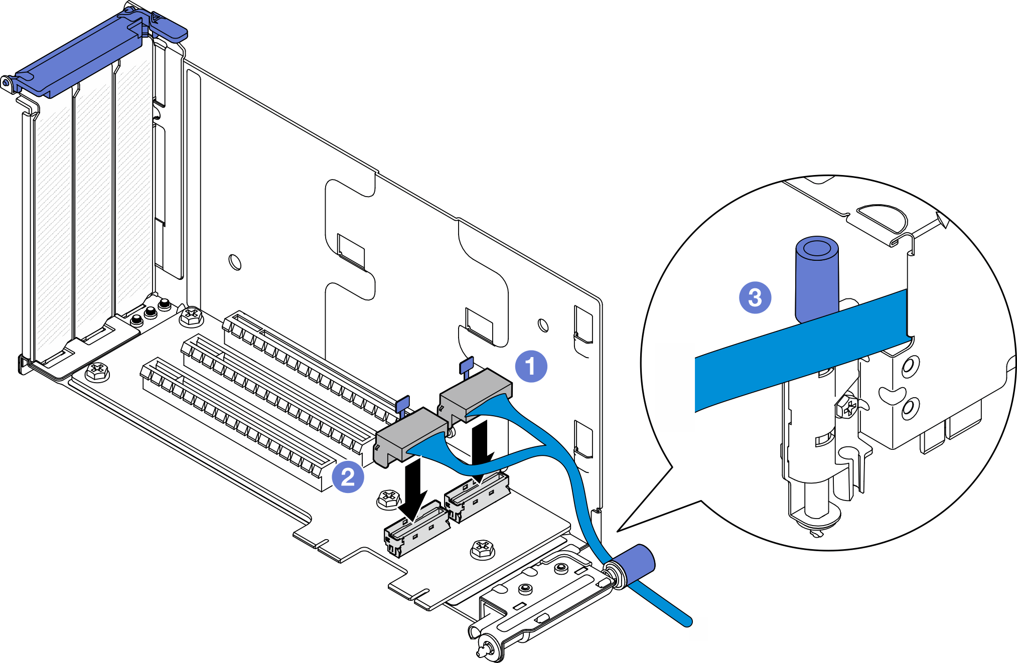
- Connect the silver signal cable to PCIe riser 1.
- Connect the cable to MCIO2 connector.
- Connect the cable to MCIO1 connector.
Figure 3. PCIe riser 1 cable routing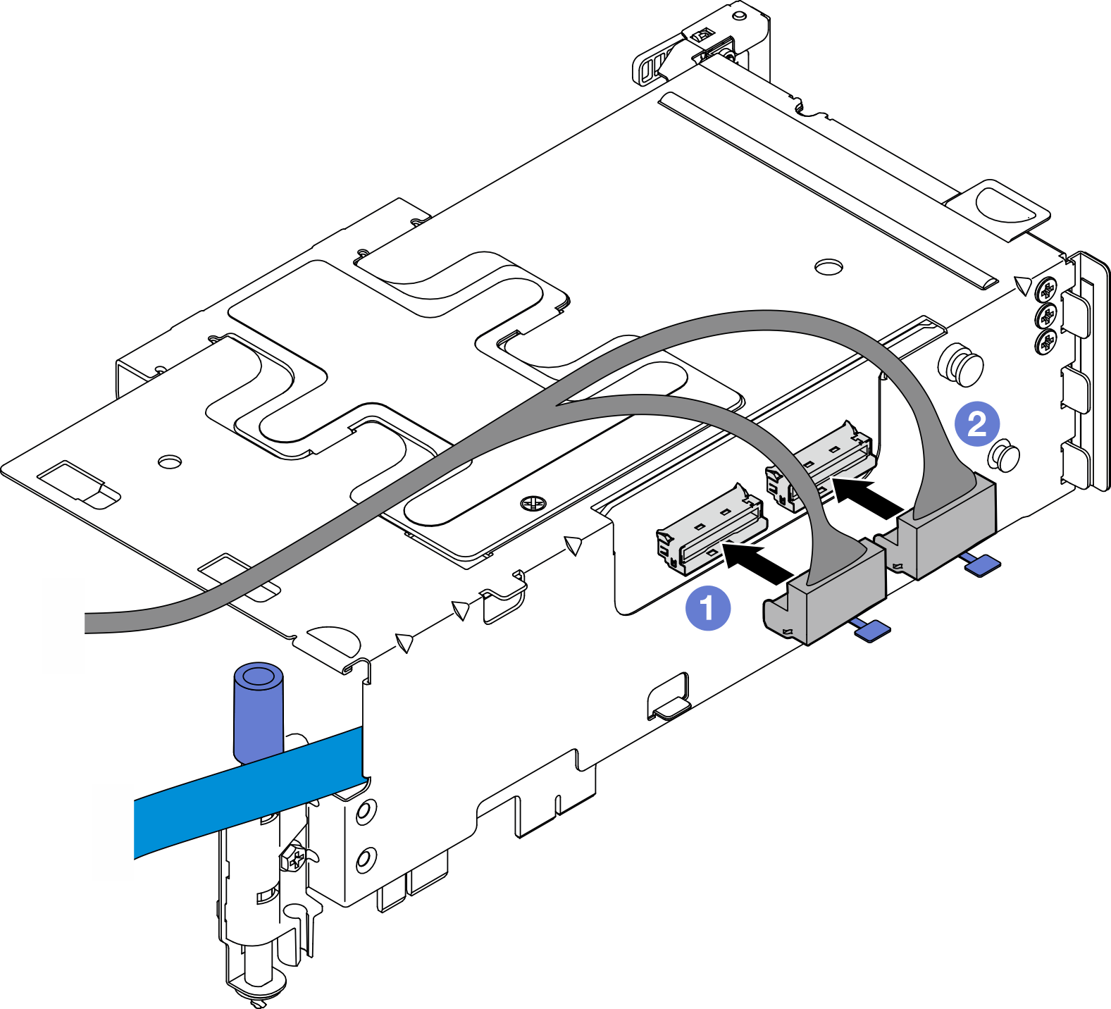
After this task is completed
Proceed to install PCIe adapters. See Install a PCIe adapter.
Complete the parts replacement. See Complete the parts replacement.
Demo Video
Install the PCIe riser card to PCIe riser 2
Procedure
- Align the holes on the riser card with the guide pins on the riser cage; then, fasten four screws to secure the riser card.Figure 4. Installing the riser card
- Connect power and signal cables to PCIe riser 2. The number of signal cables varies by configuration.
- (Optional) Connect the blue signal cable to MCIO3 and MCIO4 connectors. Press 2 the cable clip to disengage it from the slot; then, route the cable into the cable clips.Note
The blue signal cable is not supported in the following configurations:
- Front SATA drive backplane and internal NVMe drive backplane connect to the system board
- Front NVMe drive backplane and internal NVMe drive backplane connect to the system board
Figure 5. PCIe riser 2 cable routing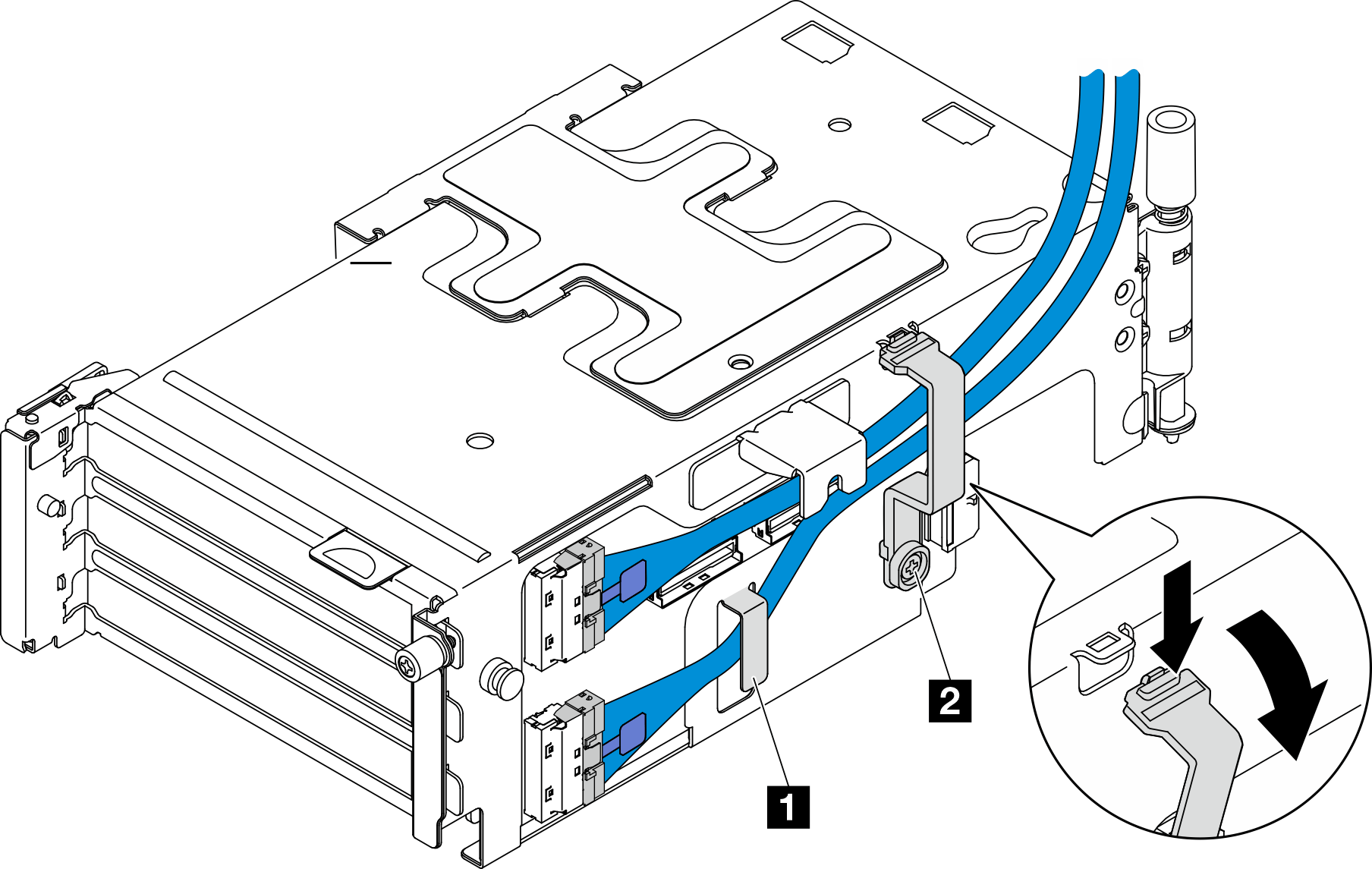
1 2 Cable clips - Connect 2 the power cable to the power connector.NoteRoute the power cable inwards as shown. Do not place the silver signal cable between the power cable and the riser cage.Figure 6. PCIe riser 2 cable routing
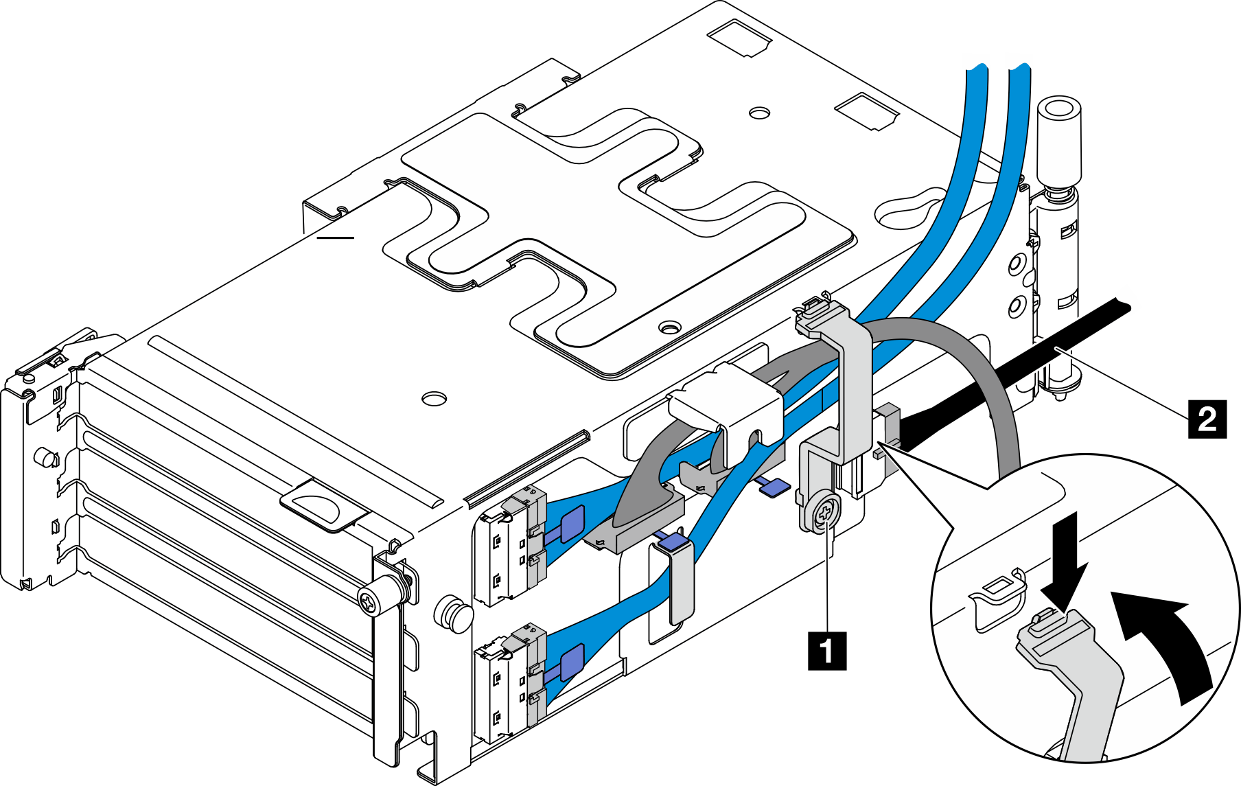
1 Cable clip 2 Power cable
- (Optional) Connect the blue signal cable to MCIO3 and MCIO4 connectors. Press 2 the cable clip to disengage it from the slot; then, route the cable into the cable clips.
After this task is completed
Proceed to install PCIe adapters. See Install a PCIe adapter.
Complete the parts replacement. See Complete the parts replacement.
Demo Video