
Power distribution board (PDB) and fan control board (FCB) cable routing

Follow the instructions in this section to learn how to do cable routing for the power distribution board (PDB) and fan control board (FCB).

This section provides cable routing instructions for the following cables:

CableFromTo
1 FCB sideband cable, 120mmFCB: Fan sideband connectorSystem board: Fan signal connector (FCB Sideband)
2 System-board power 2 cable, 220mmPDB: System board power connector 2System board: System board power 2 connector (PDB PWR 2)
3 FCB power cable, 150mmFCB: Fan power connectorPDB: Fan power connector
4 PDB sideband cable, 250mmPDB: PDB sideband connectorSystem board: Power distribution board signal connector (PDB Sideband)
5 System-board power 1 cable, 200mmPDB: System board power connector 1System board: System board power 1 connector (PDB PWR 1)

Complete the following procedure to route the cables properly.

Procedure

Figure 1. PDB and FCB cable routing

  1. Connect 1 FCB sideband cable to the following connectors:
    • 1a Fan sideband connector on the fan control board
    • 1b Fan signal connector (FCB Sideband) on the system board
    Note
    Do not route cable 1 into any cable clip.
  2. Connect 2 System-board power 2 cable to the following connectors:
    • 2a System board power connector 2 on the PDB
    • 2b System board power 2 connector (PDB PWR 2) on the system board
    Note
    Place cable 2 above cable 1.
  3. Connect 3 FCB power cable to the following connectors:
    • 3a Fan power connector on the fan control board
    • 3b Fan power connector on the PDB
  4. Install the flash power module holder to secure cable 2 and 3 under the holder. See Install a RAID flash power module to the holder.

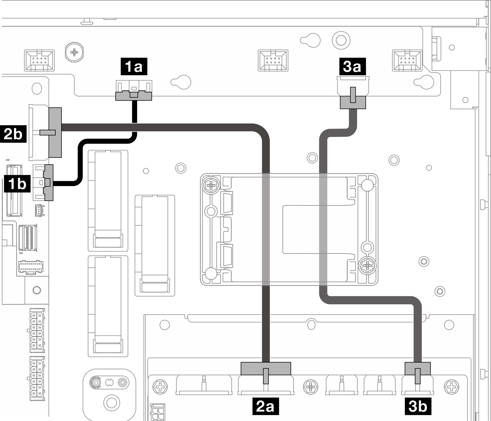
Figure 2. PDB sideband cable routing

  1. Connect 4 PDB sideband cable.
    1. Open cable clip C.
    2. Connect the cable to 4a Power distribution board signal connector (PDB Sideband) on the system board.
    3. Route the cable into cable clip C.
    4. Connect the cable to 4b PDB sideband connector on the PDB.
    5. Route the cable away from the PSU cage as shown.

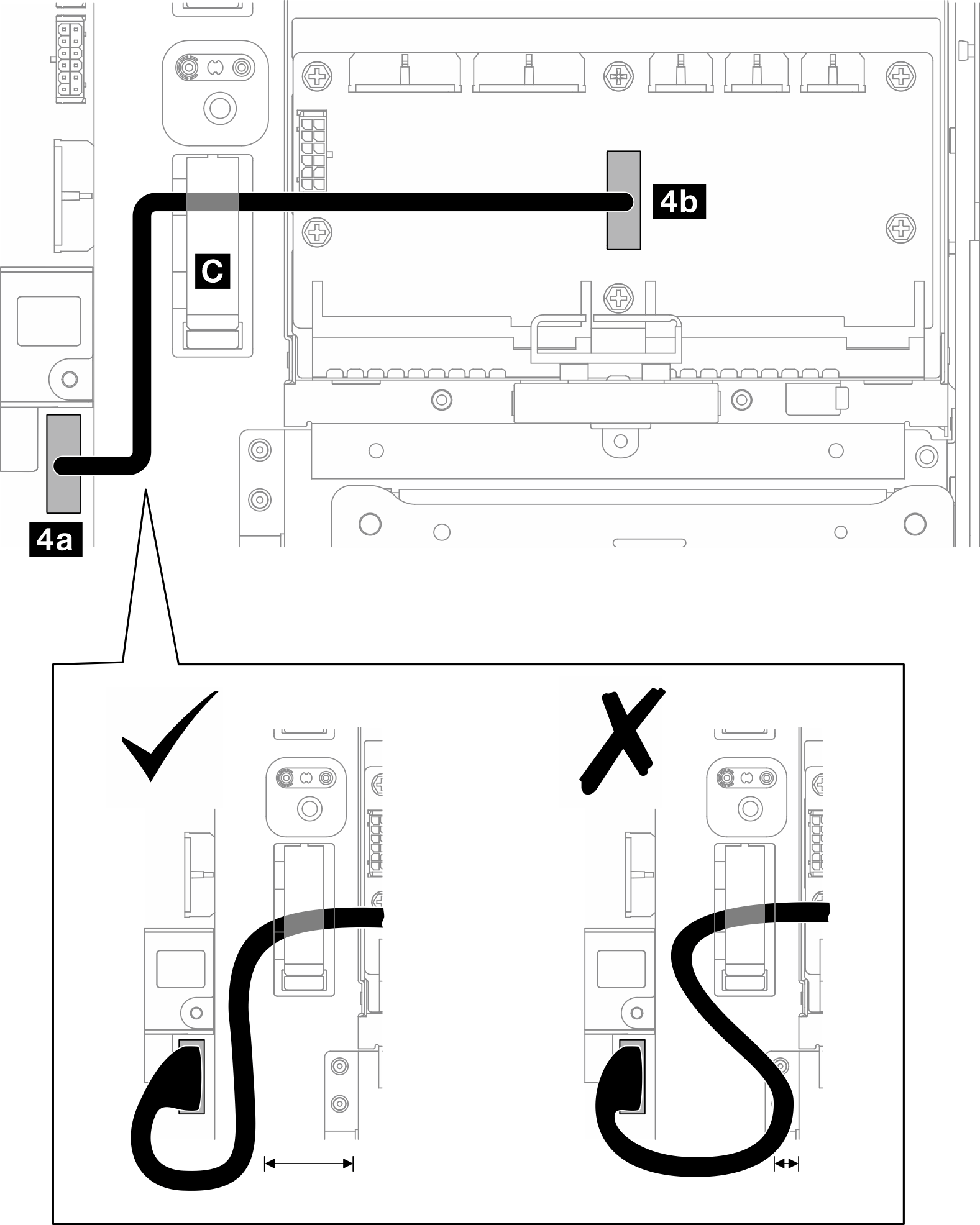
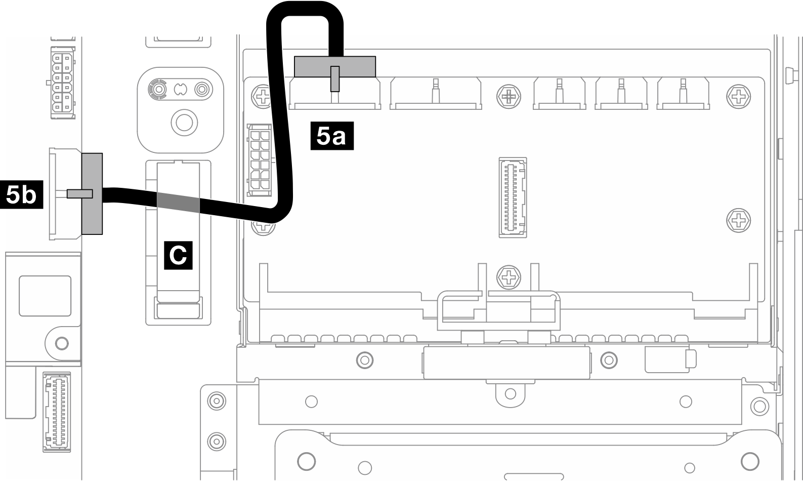
Figure 3. System-board power 1 cable routing

  1. Connect 5 System-board power 1 cable.
    1. Connect the cable to 5a System board power connector 1 on the PDB.
    2. Route the cable into cable clip C.
    3. Twist the cable as shown, and connect it to 5b System board power 1 connector (PDB PWR 1) on the system board.
    4. Close cable clip C to secure the cables.