System-board connectors for cable routing
The following illustrations show the internal connectors on the system board that are used for internal cable routing.
Figure 1. System-board connectors
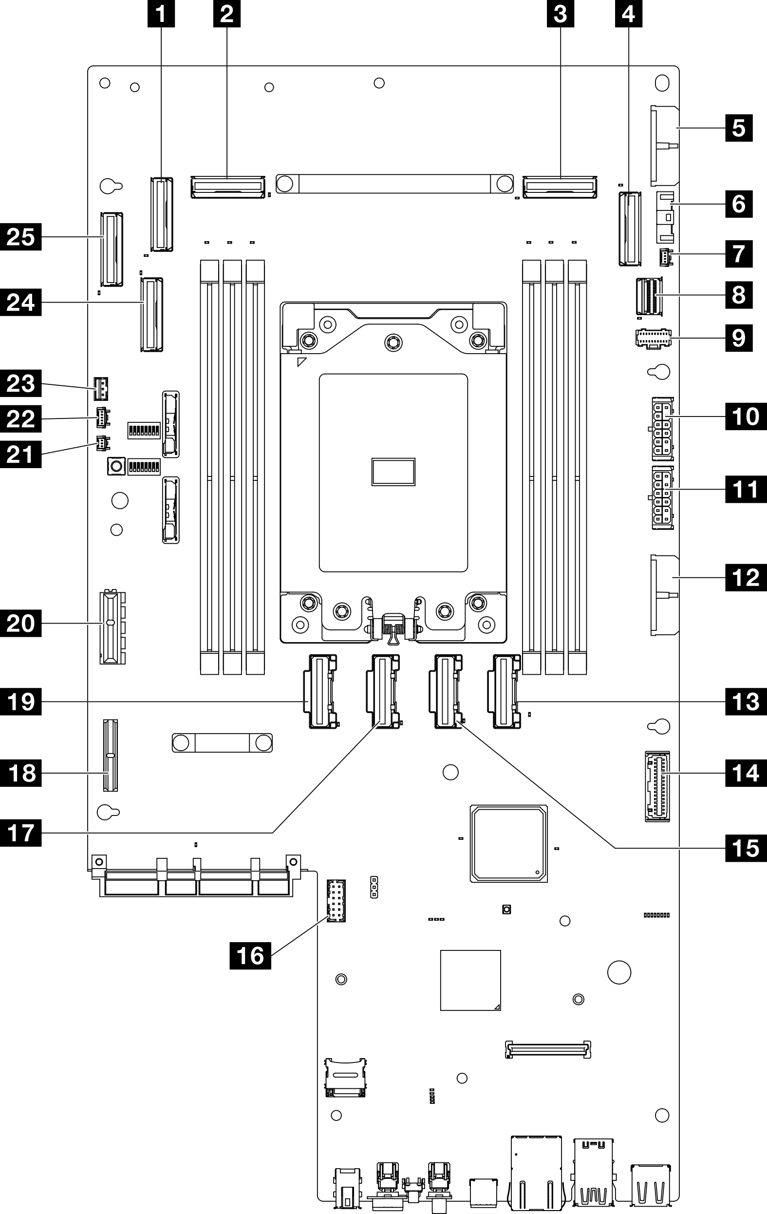
| 1 PCIe 9 connector | 14 Power distribution board signal connector (PDB Sideband) |
| 2 PCIe 8 connector | 15 PCIe 5 connector |
| 3 PCIe 3 connector | 16 Serial port connector (COM) |
| 4 PCIe 2 connector | 17 PCIe 6 connector |
| 5 System board power 2 connector (PDB PWR 2) | 18 Riser 1 power connector |
| 6 Fan signal connector (FCB Sideband) | 19 PCIe 7 connector |
| 7 Heat sink detect connector | 20 Riser 1 signal connector (Riser1 Sideband) |
| 8 M.2 signal connector (PCIe 1) | 21 Bezel detect connector |
| 9 M.2 power connector (M.2 Sideband) | 22 Air flow sensor board connector (Air Velocity Sensor) |
| 10 Internal backplane power connector | 23 Intrusion switch connector |
| 11 Front backplane power connector | 24 PCIe 10 connector |
| 12 System board power 1 connector (PDB PWR 1) | 25 PCIe 11 connector |
| 13 PCIe 4 connector |
Give documentation feedback