Drive backplane cable routing
Follow the instructions in this section to learn how to do cable routing for the drive backplanes.
Complete the following procedure to route the cables properly.
Connect BP power cables to the system board
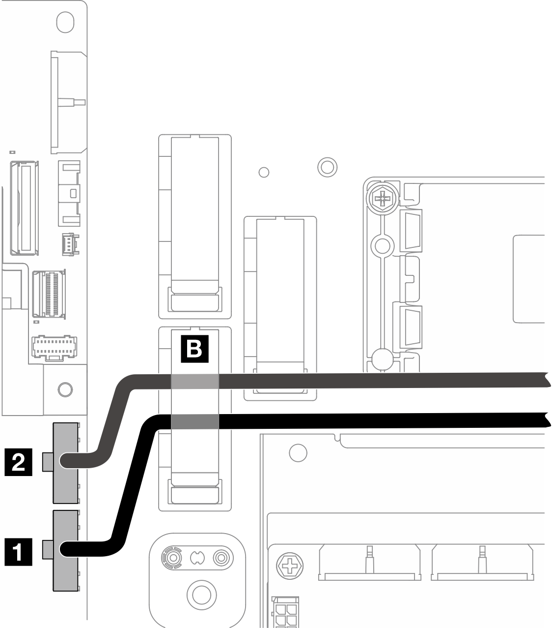
| Cable | From: system board | To |
|---|---|---|
| 1 Front BP power cable, 320mm | Front backplane power connector | Front drive backplane: power connector |
| 2 Internal BP power cable, 200mm | Internal backplane power connector | Internal drive backplane: power connector |
Connect the BP power cable(s) to the system board.
Connect the front BP power cable to 1 Front backplane power connector.
For configuration with internal drive backplane, connect the internal BP power cable to 2 Internal backplane power connector.
Secure the power cables in cable clip B.
BP signal cable routing
Proceed to the section corresponding to the selected configuration.
| Configuration | BP signal cable |
|---|---|
| RAID to front SATA + internal SATA BP | Front BP + internal BP to x350 RAID adapter:
|
Front BP + internal BP to x40 RAID adapter:
| |
Front BP to x350 RAID adapter:
| |
Front BP to x40 RAID adapter:
| |
| System board to front NVMe + internal NVMe BP |
|
| System board to front SATA + internal SATA BP | One SATA Y-cable, 520mm/400mm |
| System board to front SATA + internal NVMe BP |
|
| System board to front NVMe BP | One NVMe cable for front BP, 560mm/540mm |
| System board to front SATA BP | One SATA cable for front BP, 520mm |
| RAID to front SATA + system board to internal NVMe BP |
|
| System board to front NVMe + RAID to internal SATA BP |
|
RAID to front SATA + internal SATA BP
Install the processor air baffle. See Install the processor air baffle.
Secure the required BP signal cables in cable clip C.
Figure 2. Cable clip C
x40 RAID adapter: one signal cable to C0 connector
x350 RAID adapter:
Front BP only: one signal cable to C0 connector
Front and internal BP: two signal cables
C0 connector to front BP
C1 connector to internal BP
Proceed to connect the BP signal cable(s) to the RAID adapter on PCIe riser assembly, and install the assembly. See Install the PCIe riser assembly.
Proceed to Complete the BP cable routing.
System board to front NVMe + internal NVMe BP
- Connect the internal BP signal cable to the connectors on the system board in the following order:
PCIe 2
PCIe 3
Figure 3. Internal BP signal cable NoteBend the cable as shown.Figure 4. Internal BP signal cable
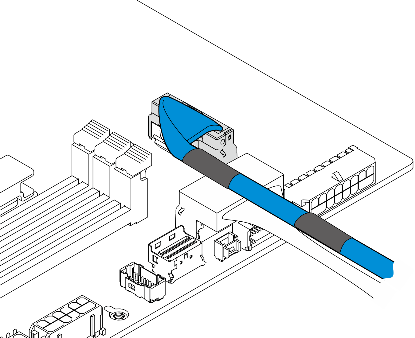
Secure the internal BP signal cable into cable clip A.
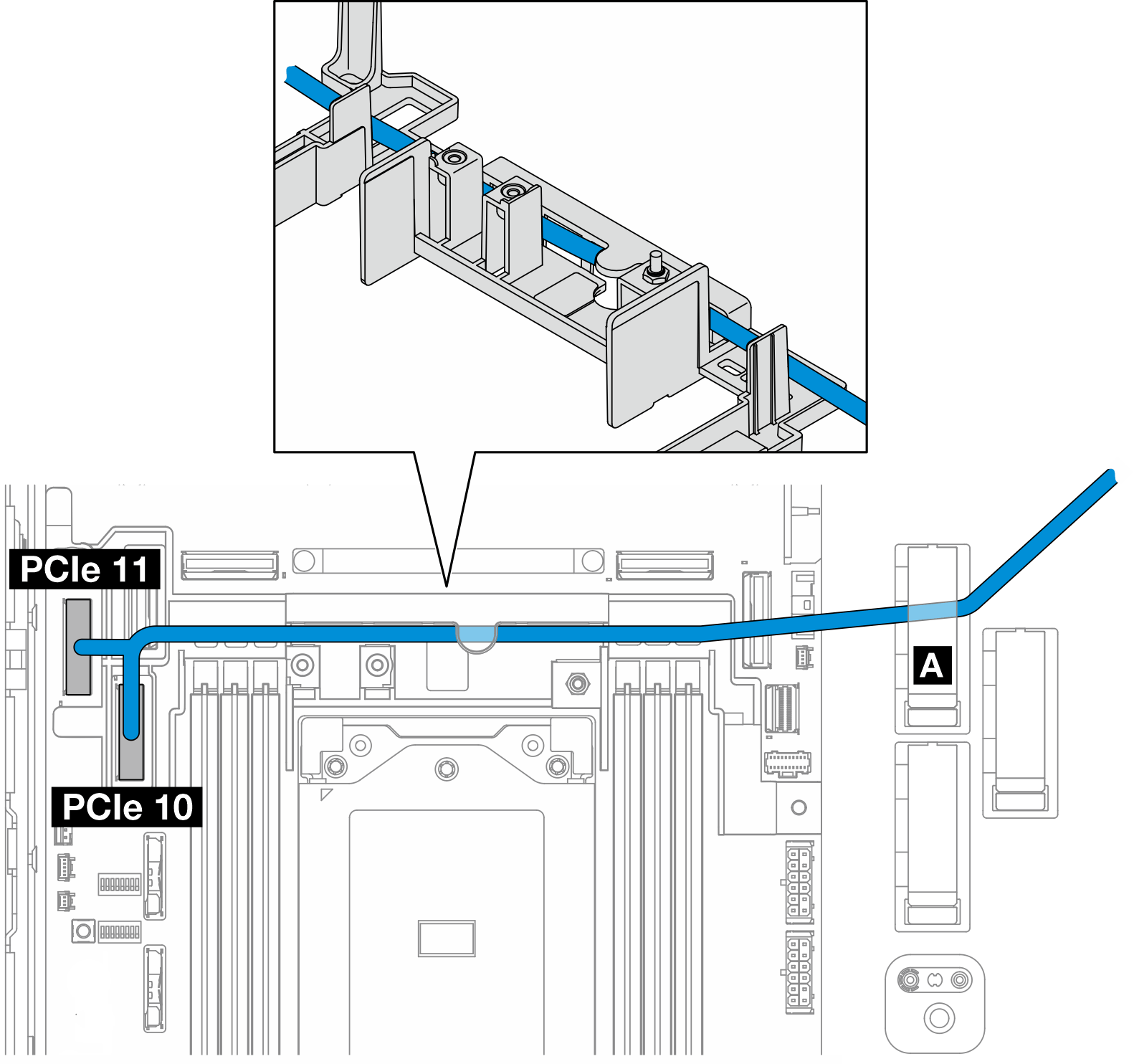
- Connect the front BP signal cable to the connectors on the system board in the following order:
PCIe 11
PCIe 10
Figure 5. Front BP signal cable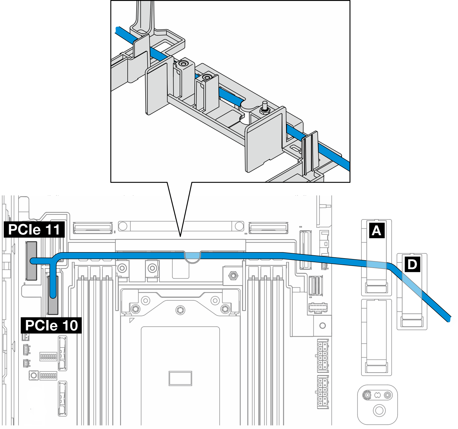
Route the front BP signal cable through the cable wall; then, secure the cable into cable clip A and D.
Install the processor air baffle. See Install the processor air baffle.
Install the PCIe riser assemblies. See Install the PCIe riser assembly.
Proceed to Complete the BP cable routing.
System board to front SATA + internal SATA BP
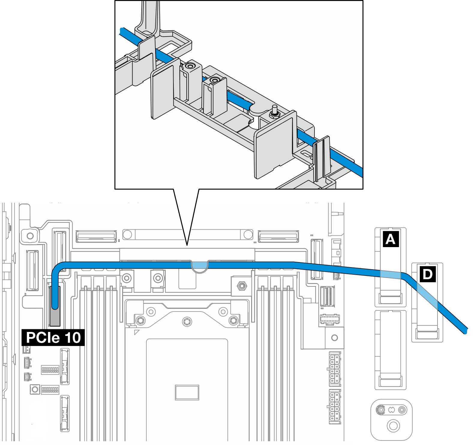
Connect the BP signal cable to PCIe 10 connector on the system board.
Route the BP signal cable through the cable wall.
Secure the internal BP signal cable into cable clip A.
Secure the front BP signal cable into cable clip A and D.
Install the processor air baffle. See Install the processor air baffle.
Install the PCIe riser assemblies. See Install the PCIe riser assembly.
Proceed to Complete the BP cable routing.
System board to front SATA + internal NVMe BP
- Connect the internal BP signal cable to the connectors on the system board in the following order:
PCIe 2
PCIe 3
Figure 6. Internal BP signal cableNoteBend the cable as shown.Figure 7. Internal BP signal cable Secure the internal BP signal cable into cable clip A.
Connect the front BP signal cable to PCIe 10 connector on the system board.
Route the front BP signal cable through the cable wall; then, secure the cable into cable clip A and D.
Install the processor air baffle. See Install the processor air baffle.
Install the PCIe riser assemblies. See Install the PCIe riser assembly.
Proceed to Complete the BP cable routing.
System board to front NVMe BP
- Connect the front BP signal cable to the connectors on the system board in the following order:
PCIe 11
PCIe 10
Figure 8. Front BP signal cable Route the front BP signal cable through the cable wall; then, secure the cable into cable clip A and D.
Install the processor air baffle. See Install the processor air baffle.
Install the PCIe riser assemblies. See Install the PCIe riser assembly.
Proceed to Complete the BP cable routing.
System board to front SATA BP
Connect the front BP signal cable to PCIe 10 connector on the system board.
Route the front BP signal cable through the cable wall; then, secure the cable into cable clip A and D.
Install the processor air baffle. See Install the processor air baffle.
Install the PCIe riser assemblies. See Install the PCIe riser assembly.
Proceed to Complete the BP cable routing.
RAID to front SATA + system board to internal NVMe BP
- Connect the internal BP signal cable to the connectors on the system board in the following order:
PCIe 11
PCIe 10
Route the internal BP signal cable through the cable wall; then, secure the cable into cable clip A.
NoteRoute one cable branch through the cable wall first; then, route the other through the cable wall.Secure the front BP signal cable in cable clip C.
Figure 9. Cable clip CInstall the processor air baffle. See Install the processor air baffle.
Proceed to connect the front BP signal cable to C0 connector of the RAID adapter on PCIe riser assembly, and install the assembly. See Install the PCIe riser assembly.
Proceed to Complete the BP cable routing.
System board to front NVMe + RAID to internal SATA BP
- Connect the front BP signal cable to the connectors on the system board in the following order:
PCIe 11
PCIe 10
Figure 10. Front BP signal cable Route the front BP signal cable through the cable wall; then, secure the cable into cable clip A and D.
NoteRoute one cable branch through the cable wall first; then, route the other through the cable wall.Secure the internal BP signal cable in cable clip C.
Figure 11. Cable clip CInstall the processor air baffle. See Install the processor air baffle.
Proceed to connect the internal BP signal cable to C0 connector of the RAID adapter on PCIe riser assembly, and install the assembly. See Install the PCIe riser assembly.
Proceed to Complete the BP cable routing.
Complete the BP cable routing
Manage the front backplane cables
Install the front drive backplane. See Install the front drive backplane.
NoteFor configurations with front and internal drive backplanes, and both the backplanes connect to x350 RAID adapter, make sure to connect the signal cable fromC0 connector of the RAID adapter to the front backplane. - Figure 12. Front drive backplane cable routing
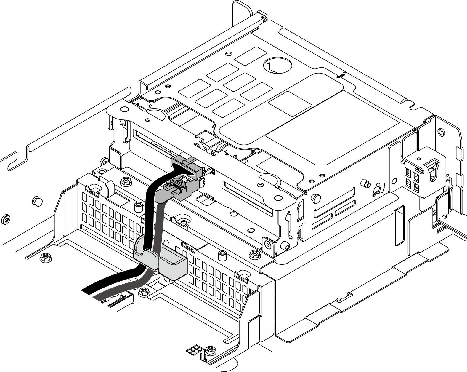
Make sure the front drive backplane cables are secured in the cable clip on the front drive cage. If necessary, route the front backplane power cable into the cable clip; then, route the front backplane signal cable into the cable clip.
- Figure 13. Front drive backplane cable routing
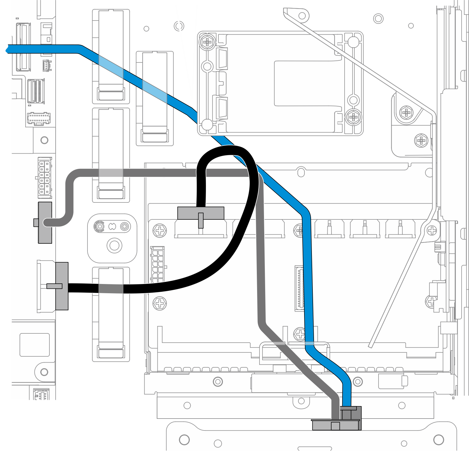
Route the front BP cables.
For the configuration with front BP signal cable connected to the system board, route the front BP signal cable under the corner of the flash power module holder.
Route the front BP power cable under System-board power 1 cable.
For configuration with internal drive backplane, proceed to Manage the internal BP cables
For configuration without internal drive backplane, press down the blue signal cable of PCIe riser 2, and make sure the cable is under the cable clip on the processor air baffle.
(Optional) Manage the internal BP cables
Complete the following procedures in the listed order to manage the internal BP cables.
Install the internal drive cage. See Install the internal drive cage.
Install the internal drive backplane. See Install the internal drive backplane.