Install the PCIe riser assembly
Follow the instructions in this section to install the PCIe riser assembly.
S002
CAUTION
The power-control button on the device and the power switch on the power supply do not turn off the electrical current supplied to the device. The device also might have more than one power cord. To remove all electrical current from the device, ensure that all power cords are disconnected from the power source.
About this task
Attention
Read Installation Guidelines and Safety inspection checklist to ensure that you work safely.
Power off the server and peripheral devices and disconnect the power cords and all external cables. See Power off the server.
Touch the static-protective package that contains the component to any unpainted metal surface on the server; then, remove it from the package and place it on a static-protective surface.
Note
Depending on the configuration, the PCIe riser assembly might look slightly different from the illustration in this section.
Procedure
Install PCIe riser 1
Procedure
- Make sure the signal cables of PCIe riser 1 are routed properly.
- Route the blue signal cable along the intrusion switch as shown.
- Route the silver signal cable through the cable wall. Press the cable down toward the system board to avoid interfering with the retaining clips of memory module slots.
Figure 1. PCIe riser 1 cable routing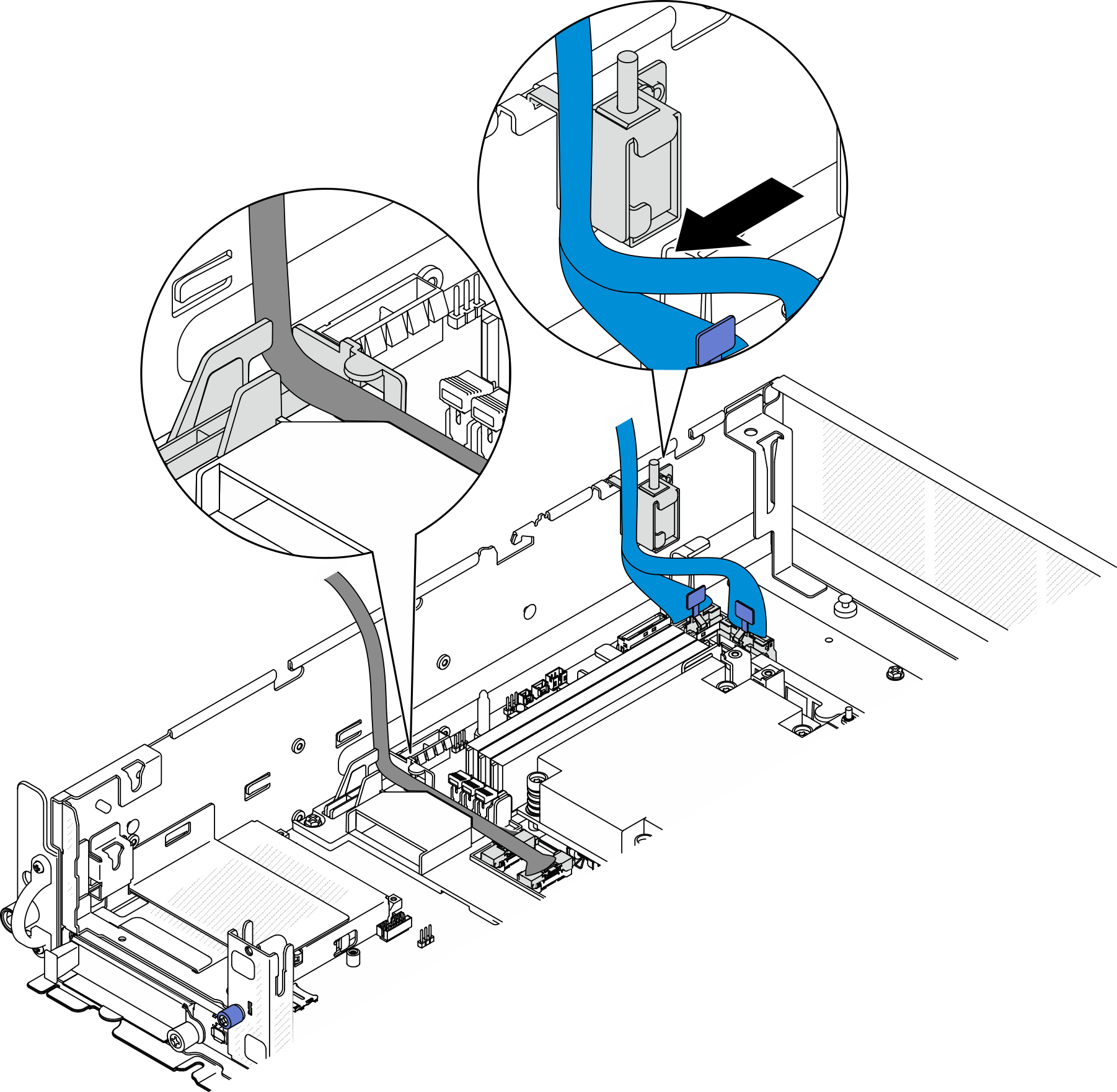
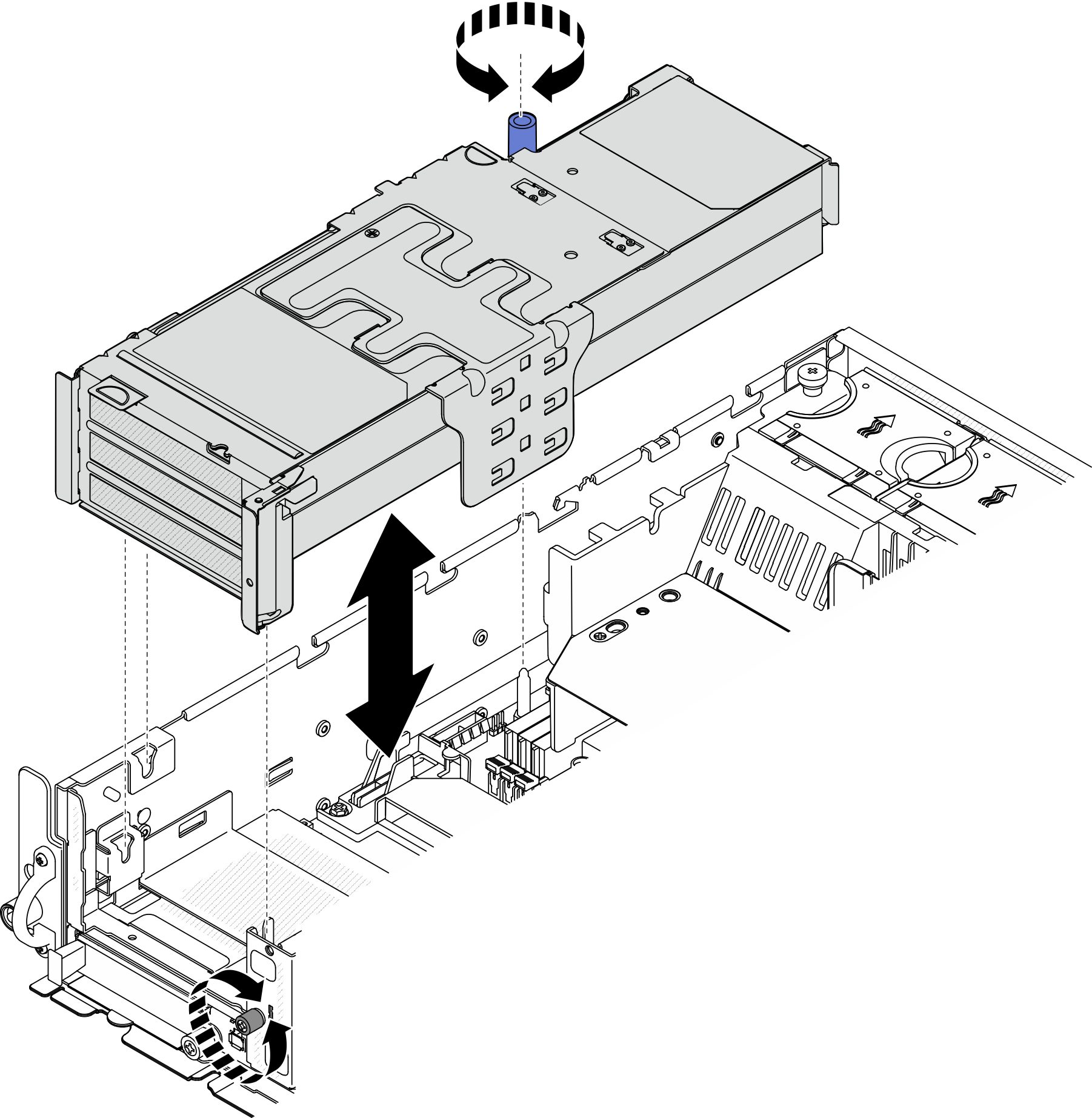
- Install PCIe riser 1.Figure 2. Installing PCIe riser 1
- Manage the signal cables.
 Manage the blue signal cable into the space between the processor air baffle and the chassis.NoteMake sure that the blue signal cable does not cover the guide slot for the top cover.
 Manage the silver signal cable into the space between PCIe riser 1 and the chassis.
Figure 3. Managing PCIe riser 1 signal cables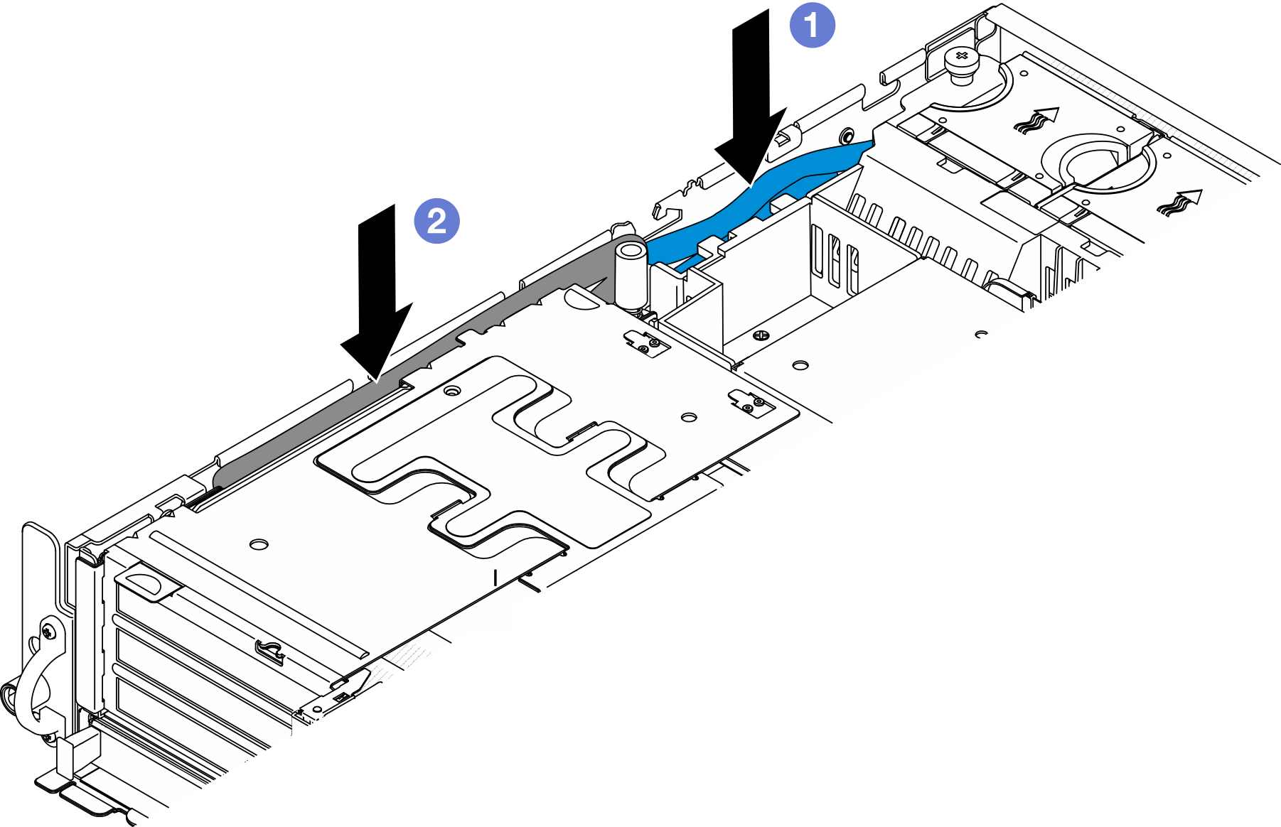
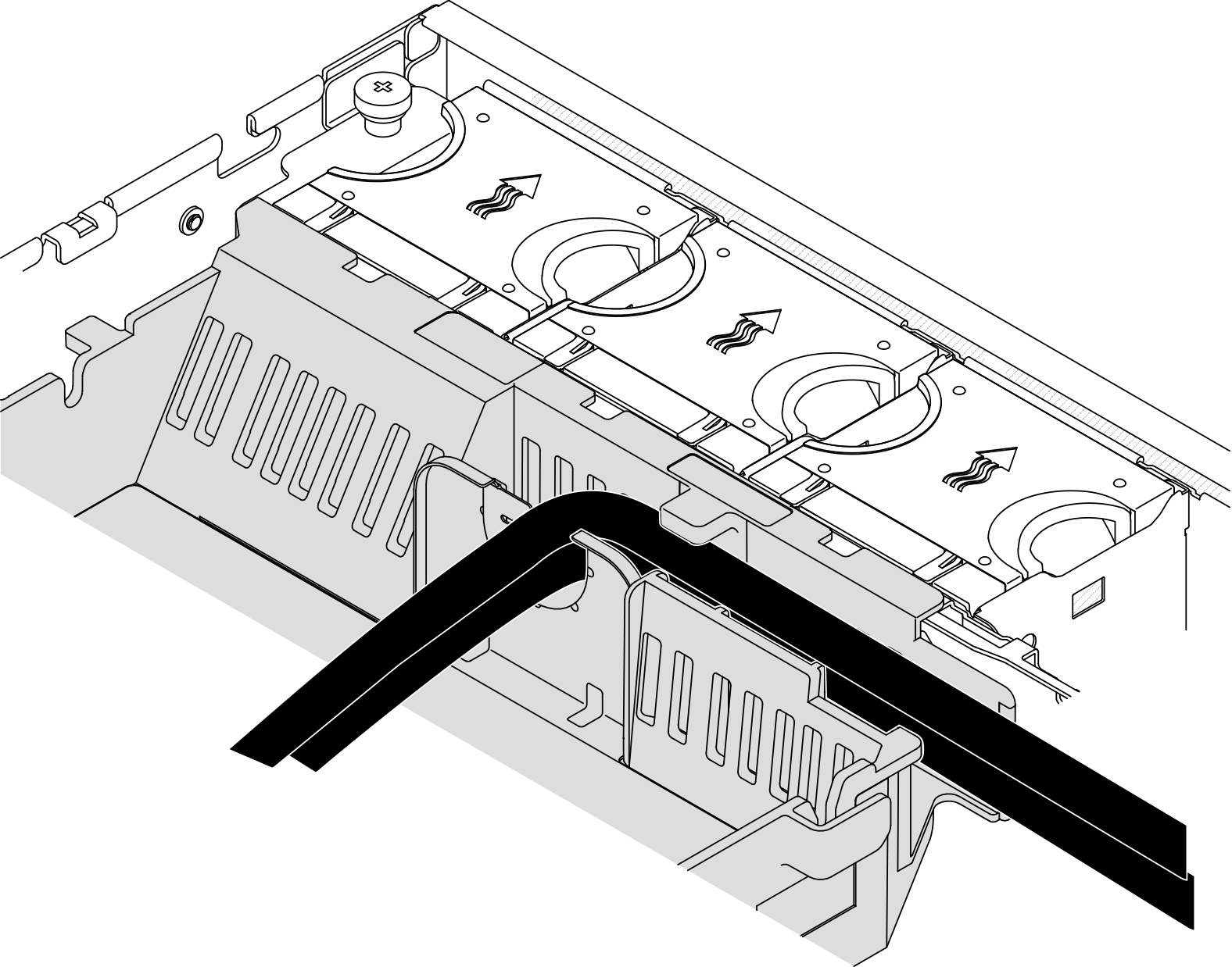
- If applicable, manage all the GPU power cables into the cable guide of the processor air baffle.Figure 4. GPU power cables on processor air baffle
Install PCIe riser 2
Procedure
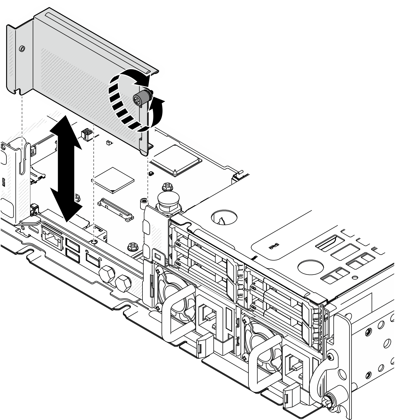
- If the riser blank filler is installed, remove the riser blank filler.Figure 5. Removing the riser blank filler
- Make sure the signal cables of PCIe riser 2 are routed properly.
- If applicable, secure the blue signal cable in cable clip A.
- Route the silver signal cable through the cable wall; then, secure the cable in cable clip C. Press the cable down toward the system board to avoid interfering with the retaining clips of memory module slots.
Figure 6. PCIe riser 2 cable routing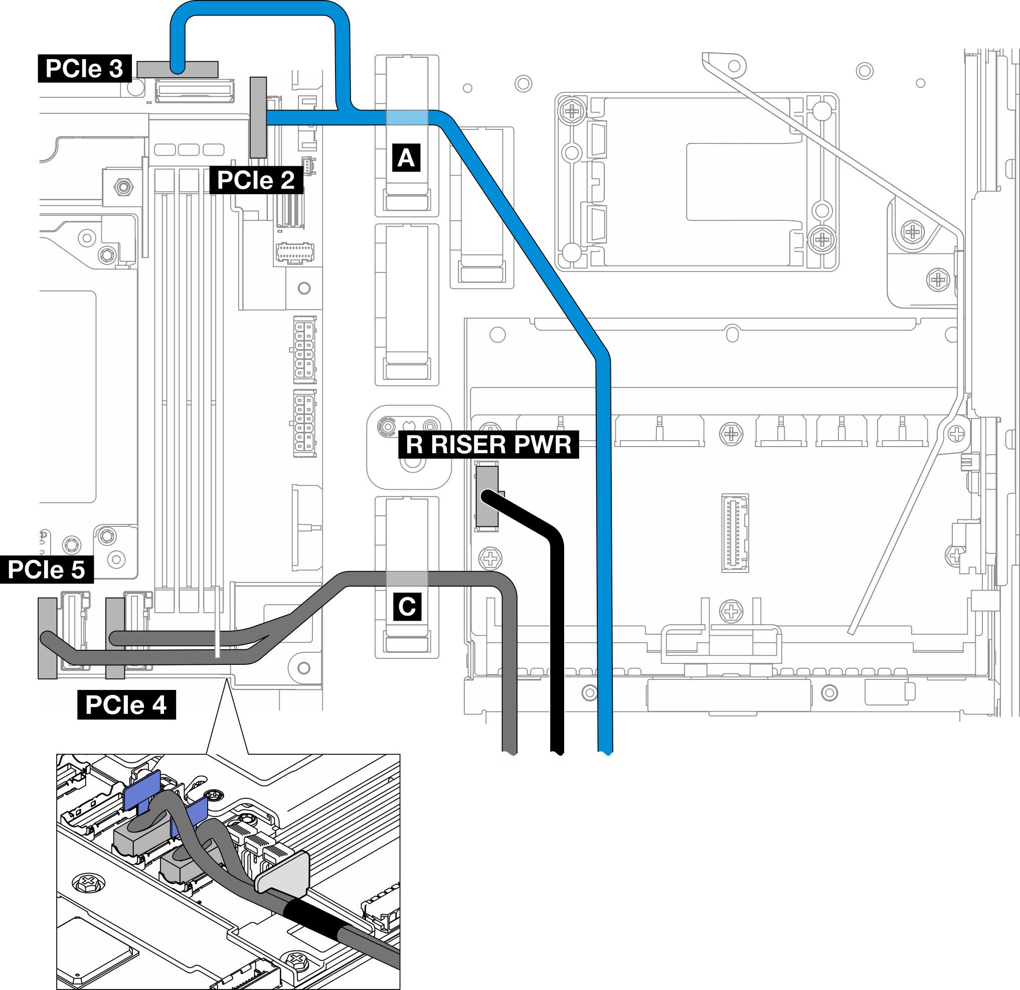
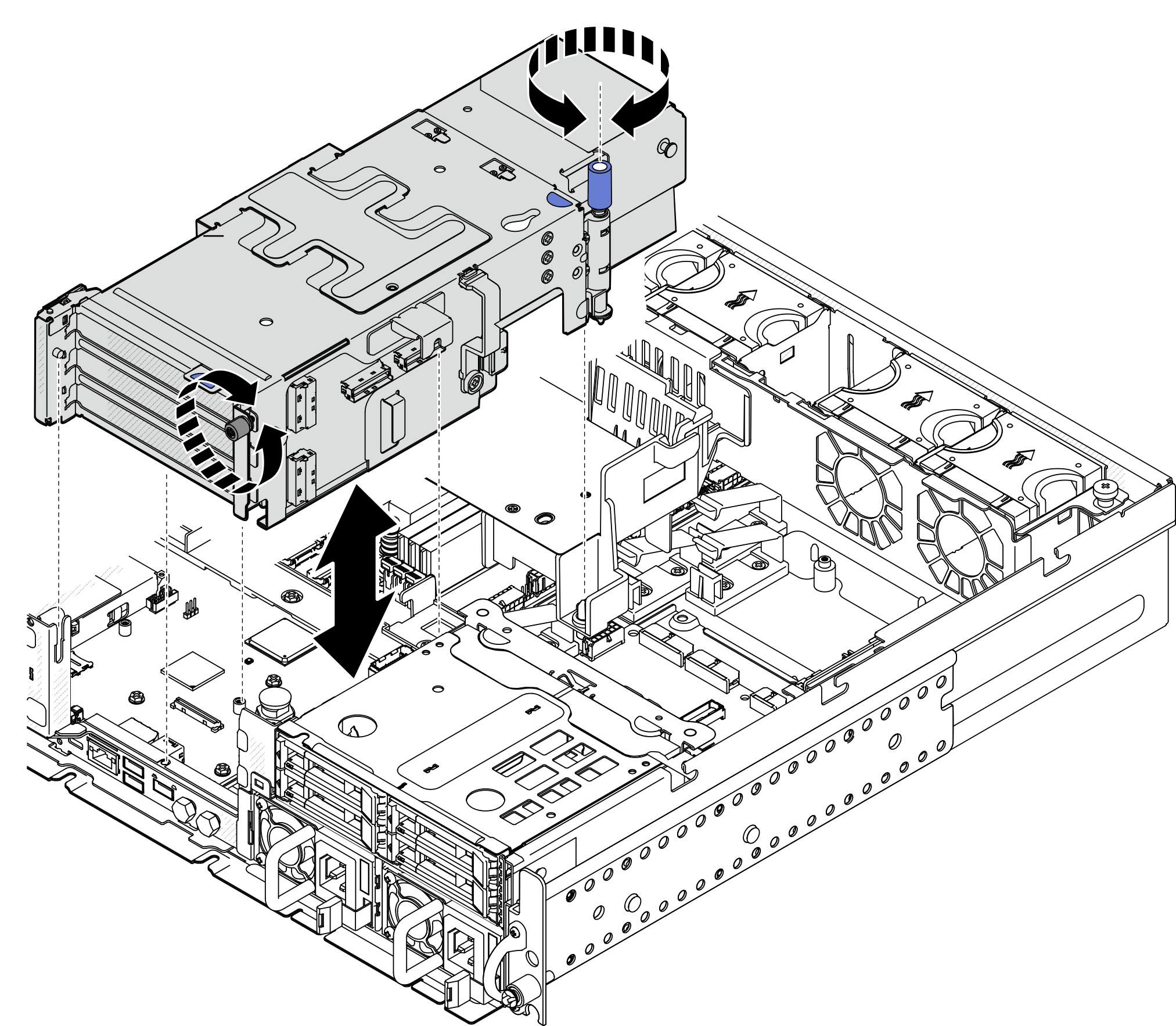
- Install PCIe riser 2.Figure 7. Installing PCIe riser 2
- If applicable, manage all the GPU power cables into the cable guide of the processor air baffle.Figure 8. GPU power cables on processor air baffle
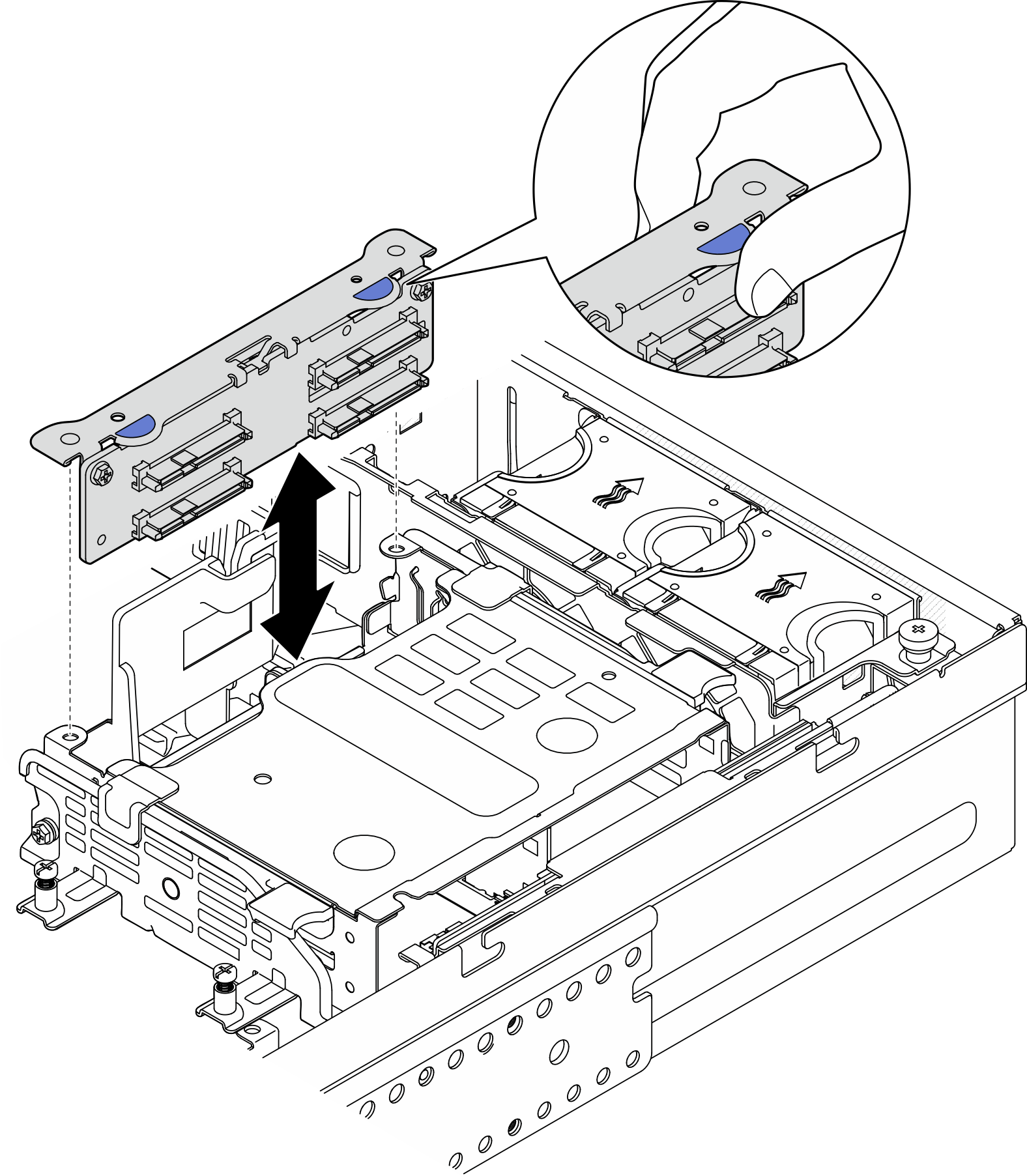
- If applicable, reinstall the internal drive backplane. Pinch the blue touch points on the backplane bracket as shown; then, press the backplane into the slot until it clicks into place.Figure 9. Installing the internal drive backplane
- If applicable, press the following cables down and make sure that the cables are under the cable clip of the processor air baffle.
Signal cable of internal drive backplane
Power cable of internal drive backplane
The blue signal cable of PCIe riser 2
Figure 10. Managing the cables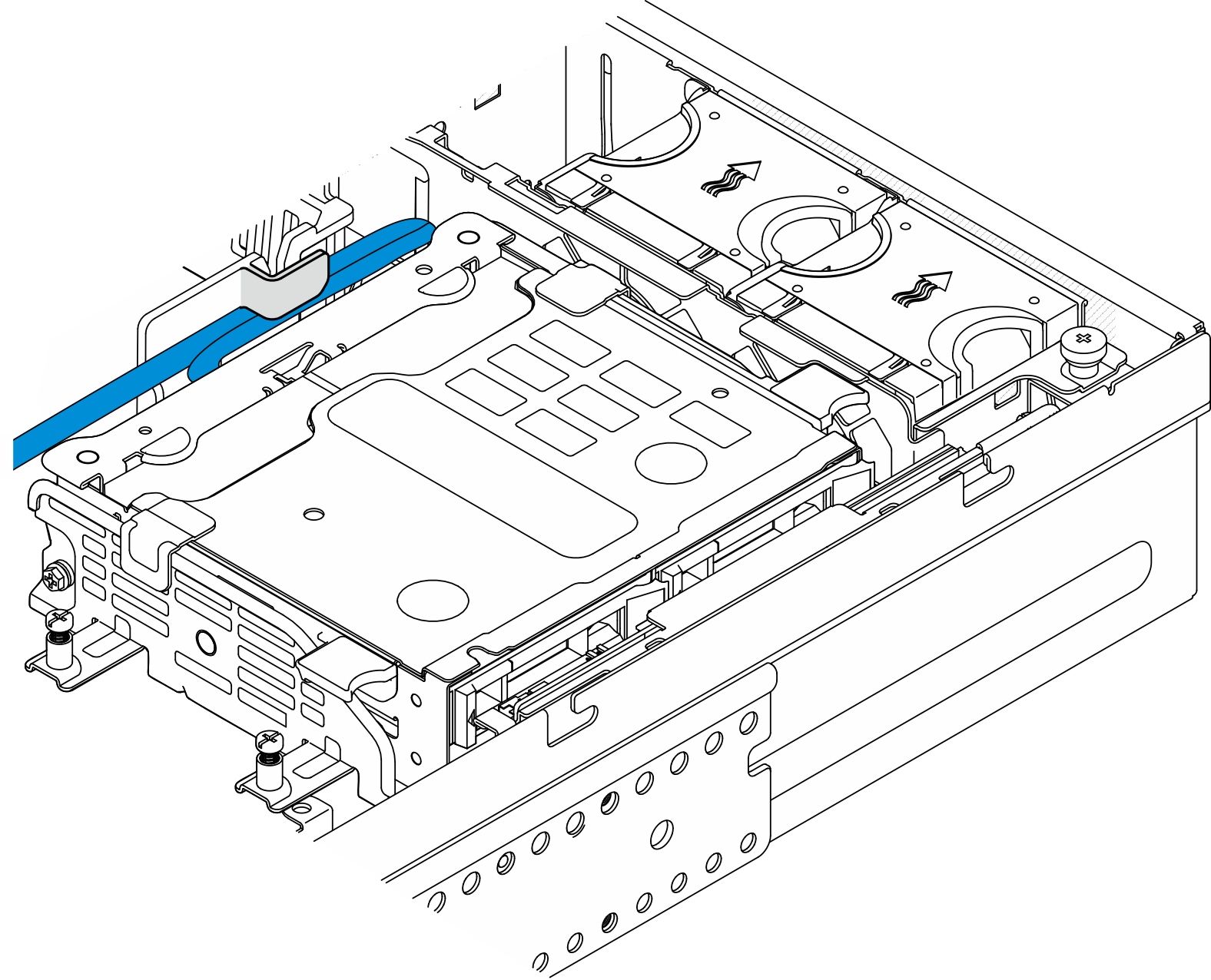
After this task is completed
Complete the parts replacement. See Complete the parts replacement.
Demo Video
Give documentation feedback