Install the front drive backplane
Follow instructions in this section to install the front drive backplane.
S002


CAUTION
The power-control button on the device and the power switch on the power supply do not turn off the electrical current supplied to the device. The device also might have more than one power cord. To remove all electrical current from the device, ensure that all power cords are disconnected from the power source.
About this task
Attention
Read Installation Guidelines and Safety inspection checklist to ensure that you work safely.
Power off the server and peripheral devices and disconnect the power cords and all external cables. See Power off the server.
Touch the static-protective package that contains the component to any unpainted metal surface on the server; then, remove it from the package and place it on a static-protective surface.
Note
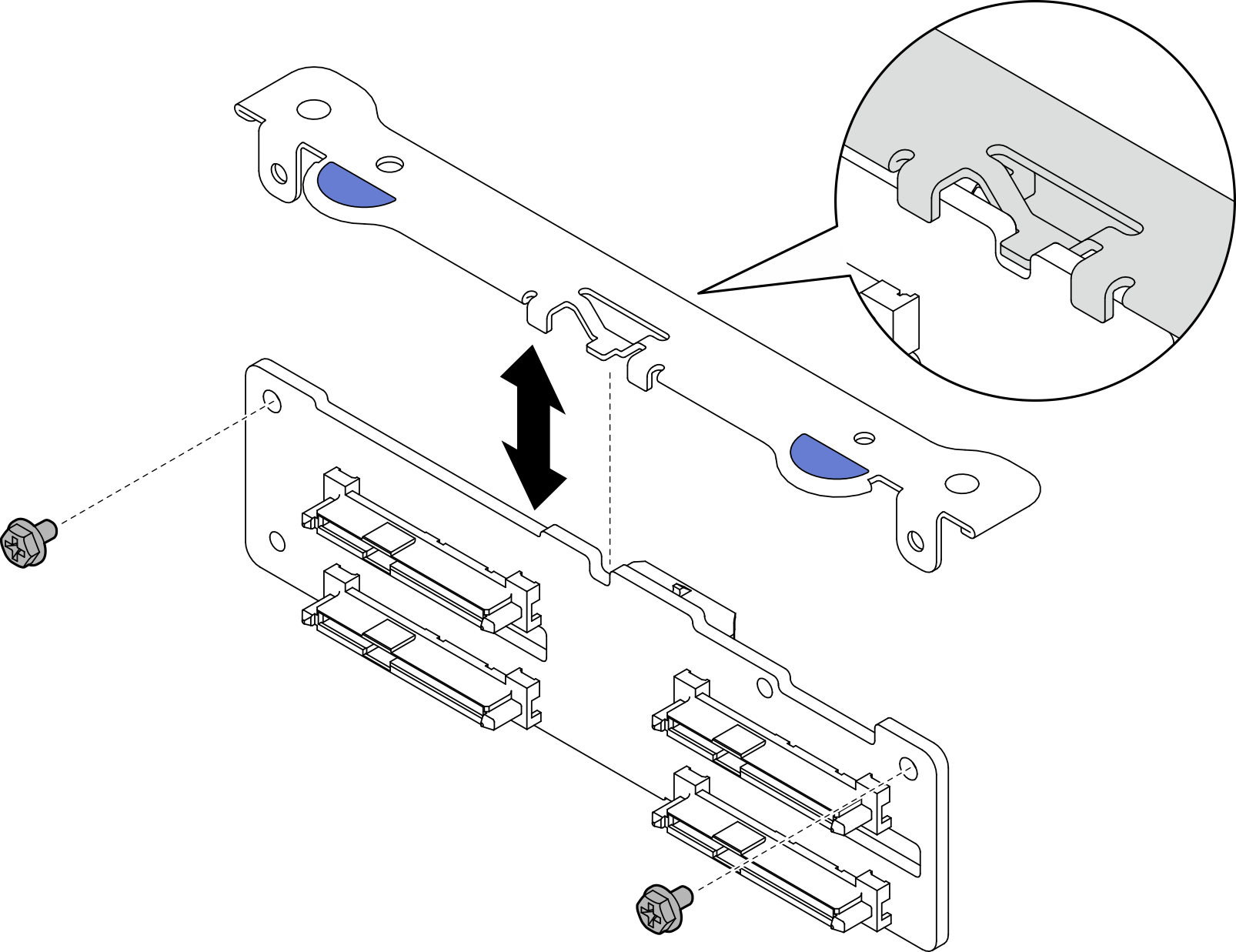
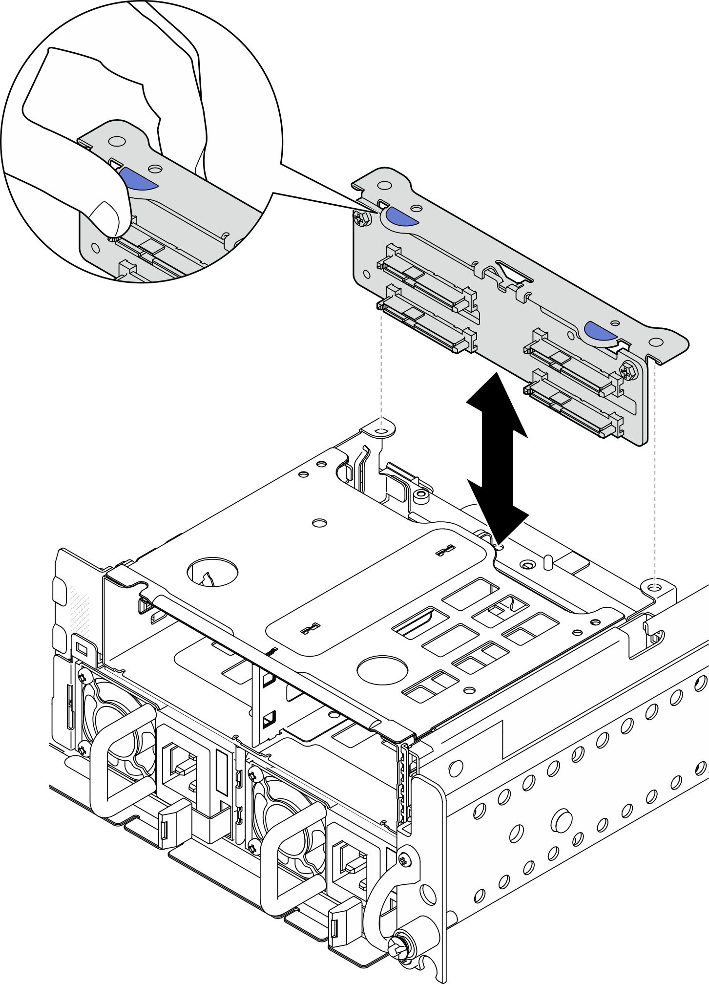
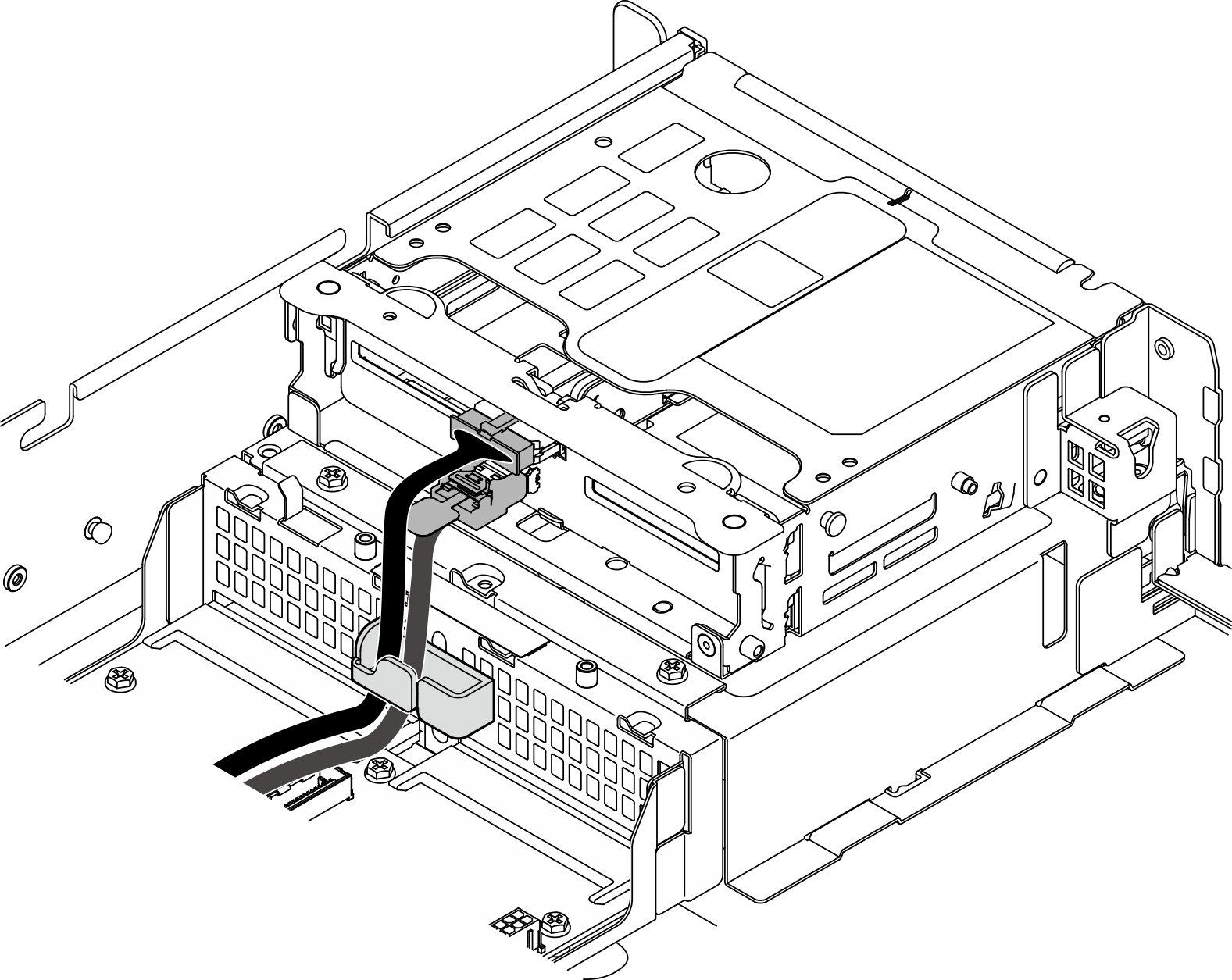
Depending on the configuration, the drive backplane might look slightly different from the illustration in this section.
Procedure
After this task is completed
Reinstall the drives and drive bay fillers (if any) into the front drive bays. See Install a front hot-swap drive.
Complete the parts replacement. See Complete the parts replacement.
Demo Video
Give documentation feedback


