M.2 backplane cable routing
Follow the instructions in this section to learn how to do cable routing for the M.2 backplane.
Proceed to the section corresponding to the selected configuration.
| Configuration | Cable |
|---|---|
| M.2 backplane to system board | For SATA/x4 NVMe M.2 backplane:
For SATA/NVMe M.2 backplane:
|
| M.2 backplane to RAID adapter | For SATA/x4 NVMe M.2 backplane:
|
To system board
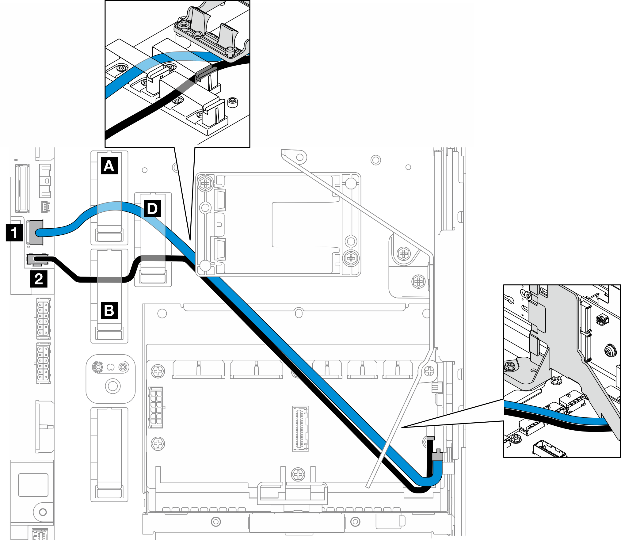
Complete the following procedure to route the cables properly.
Procedure
To RAID adapter
Figure 1. RAID adapter on PCIe riser 1

Figure 2. RAID adapter on PCIe riser 2
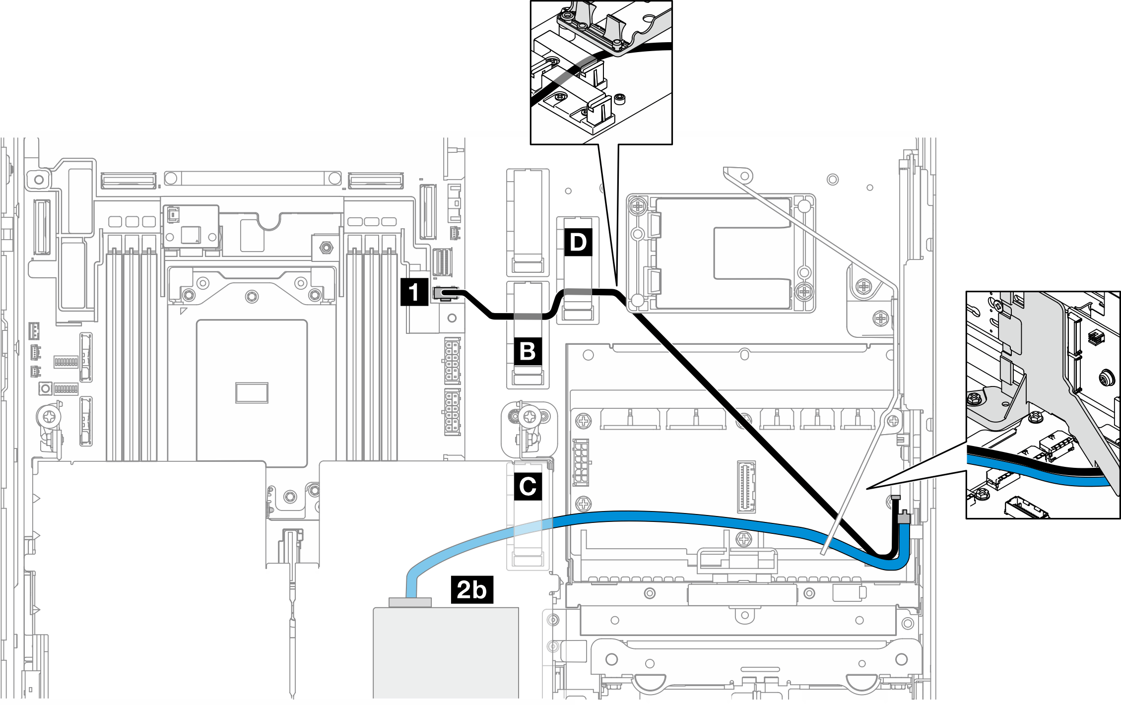
Complete the following procedure to route the cables properly.
Procedure
Give documentation feedback