Install the server to the rack
Follow instructions in this section to install the node to the rack.
About this task
S002
CAUTION
The power-control button on the device and the power switch on the power supply do not turn off the electrical current supplied to the device. The device also might have more than one power cord. To remove all electrical current from the device, ensure that all power cords are disconnected from the power source.
S036
 |  |
| 18 - 32 kg (39 - 70 lb) | 32 - 55 kg (70 - 121 lb) |
CAUTION
Use safe practices when lifting.
R006
CAUTION
Do not place any object on top of a rack-mounted device unless that rack-mounted device is intended for use as a shelf.
Attention
Read Installation Guidelines and Safety inspection checklist to ensure that you work safely.
Power off the server and peripheral devices and disconnect the power cords and all external cables. See Power off the server.
CAUTION
Make sure to have two people operate the server removal procedures to prevent injury.
Procedure
- Install the inner rails to the server.Figure 1. Installing the inner rail
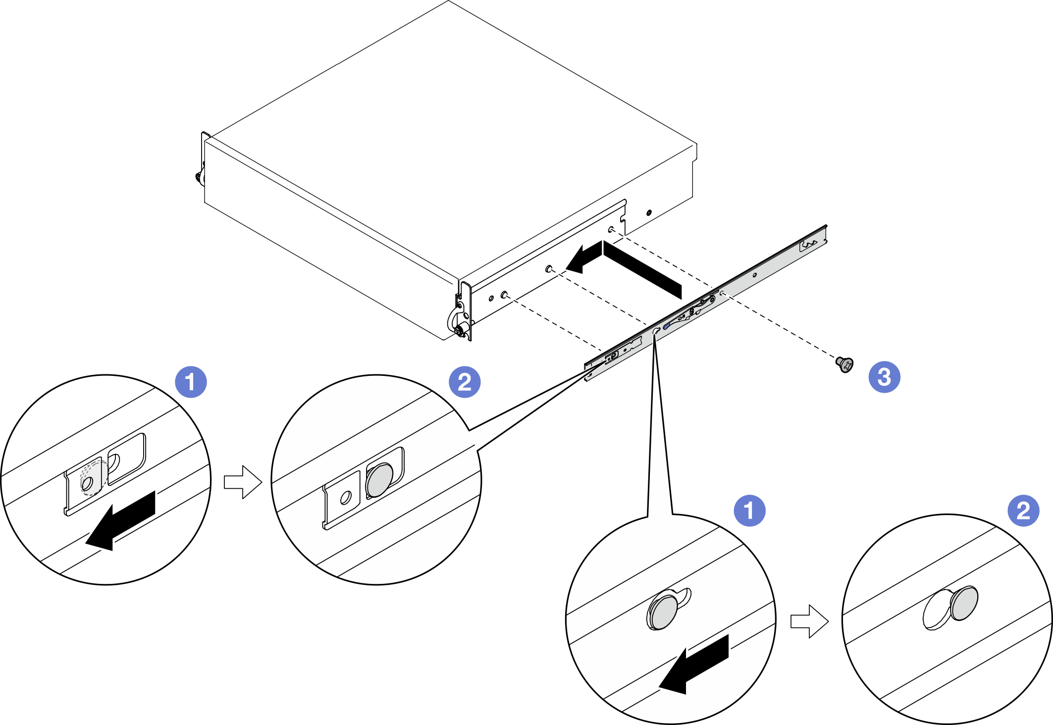 AttentionThere are “L” and “R” logos marked on the front of inner rails which represent the left rail and the right rail. Ensure correct rails are installed to the rack accordingly.
 Align the mounting holes on the inner rail with the corresponding rail mounting pins on the side of the server.
 Push the inner rail as shown until the mounting pins on the server are locked in place.
- Tighten M3.5 screws to secure the inner rail to the server.NoteThe number of screws for each inner rail varies by the rail kit and the depth of EIA brackets. See the depth mark on the side of chassis to identify the depth of EIA brackets, and refer to the following information for screw locations.Figure 2. Depth mark for EIA brackets
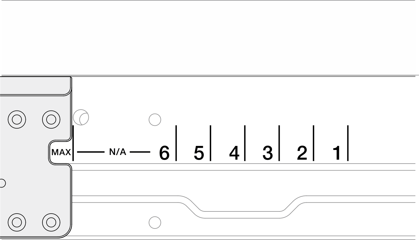
Rail kit Depth of EIA brackets The number of screws for each inner rail - ThinkEdge 600mm Ball Bearing Rail Kit
- or
- ThinkEdge 2-Post Friction Rail Kit
Any 1 - ThinkEdge 1000mm Friction Rail Kit v2
#1, #2, #3, #4 2 #5, #6, Max 3 Figure 3. One screw for the inner rail of ThinkEdge 600mm Ball Bearing Rail Kit Figure 4. One screw for the inner rail of ThinkEdge 2-Post Friction Rail Kit
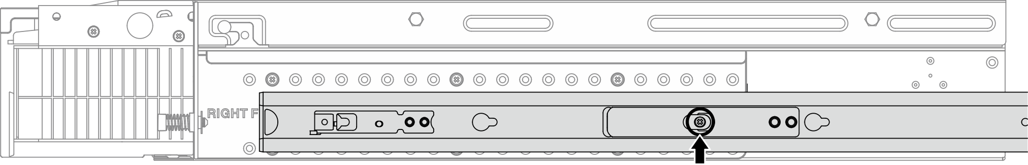 Figure 5. Two screws for the inner rail of ThinkEdge 1000mm Friction Rail Kit v2
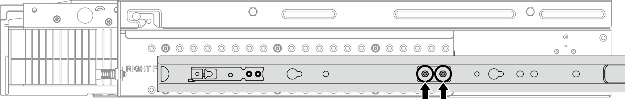 Figure 6. Three screws for the inner rail of ThinkEdge 1000mm Friction Rail Kit v2
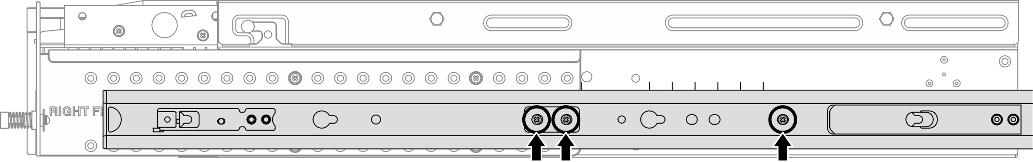
- Install the server to the rack.Figure 7. Installing the server to the rack
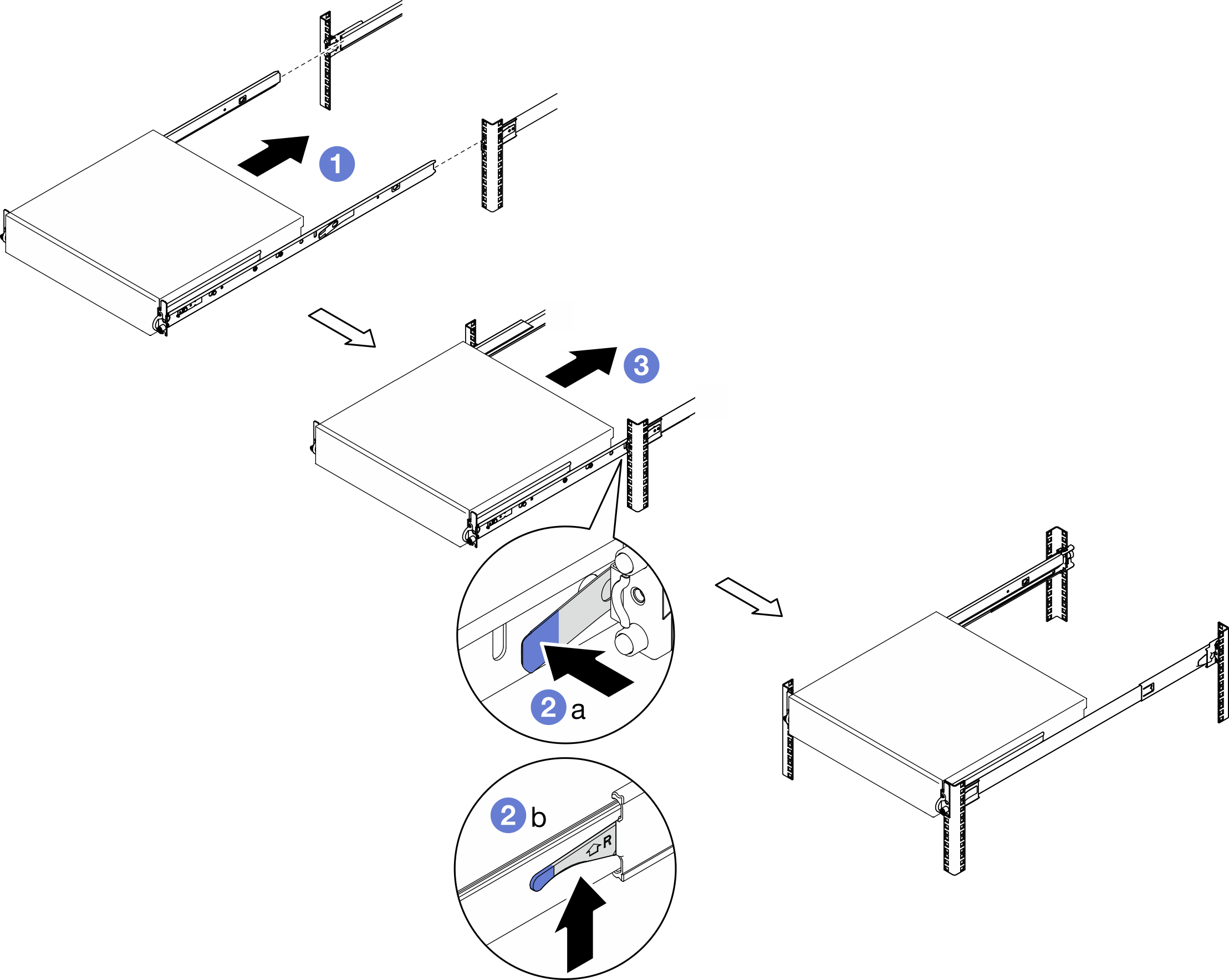
- Carefully lift the server and align the server with the rails on the rack; then, position the server as shown and push it into the rack.
- Depending on the rail kit, press or lift the release latches.
 Push the server all the way into the rack until the server locks into place with a click.
- Secure the server to the rack.
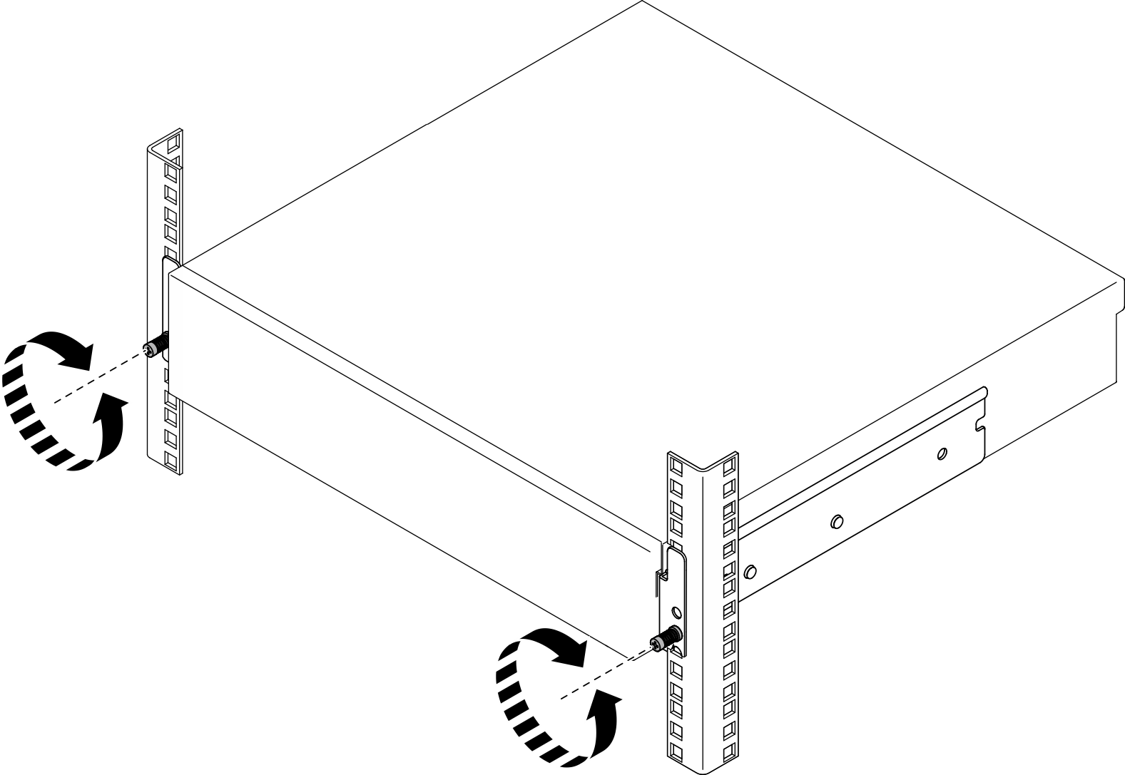
- For the configurations with standard EIA brackets, fasten the two thumbscrews.Figure 8. Securing the server to the rack: standard EIA brackets
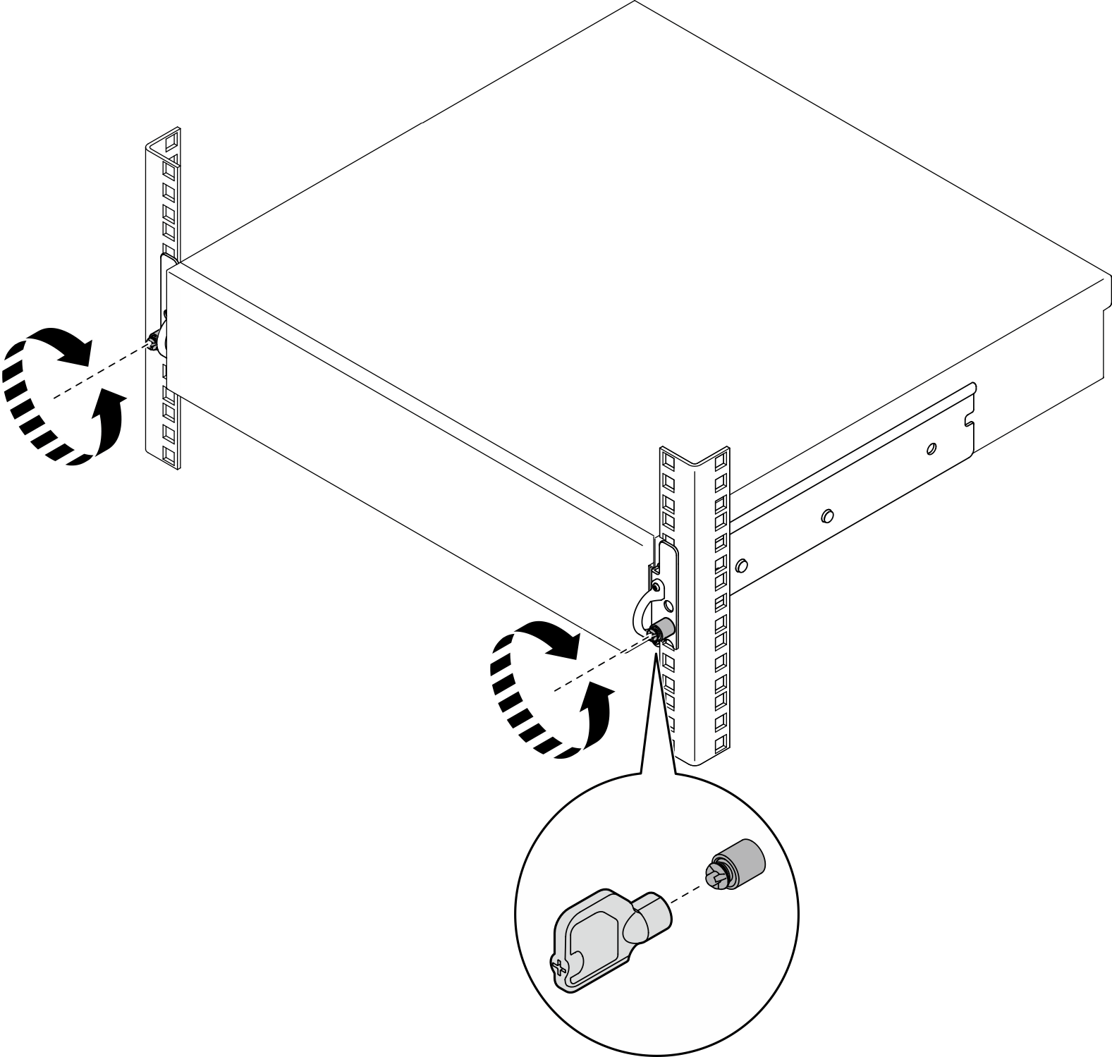
- For the configurations with security EIA brackets, fasten the two security screws with key. Store the key for future use.Figure 9. Securing the server to the rack: security EIA brackets
- For the configurations with standard EIA brackets, fasten the two thumbscrews.
After this task is completed
Reconnect the power cords and any cables that you removed.
Power on the server and any peripheral devices. See Power on the server.
If applicable, reinstall the security bezel. See Install the security bezel.
Give documentation feedback