Install an I/O expansion adapter
Use this information to install an I/O expansion adapter option.
Before you install an I/O expansion adapter, complete the following steps:
Read Installation Guidelines to ensure that you work safely.
- Carefully lay the compute node on a flat, static-protective surface, orienting the compute node with the bezel pointing toward you.
Remove the compute node cover (see Remove the compute node cover for instructions).
This component can be installed as an optional device or as a CRU. The installation procedure is the same for the optional device and the CRU.
Attention
When installing an I/O adapter in one of the I/O expansion connectors, make sure the numbers in the Hexagon and Pentagon on the I/O expansion connector (see the service labeling on top of the compute node cover for details) corresponds to the particular shape and numbering of the I/O module bay on the Flex chassis (see the bay labeling along the top and bottom edges of the chassis rear for details). If the correlation is incorrect, communication with the chassis may fail.
Figure 1. Number of I/O module bay
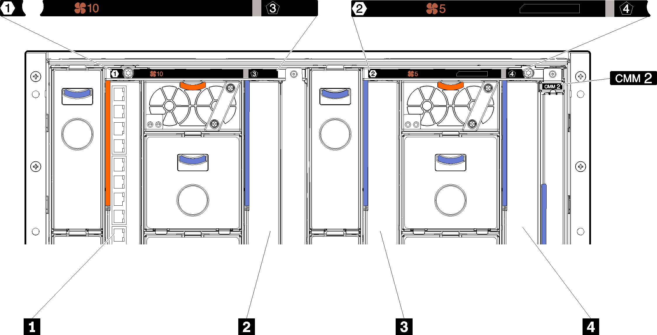
| 1 I/O module bay 1 | 3 I/O module bay 2 |
| 2 I/O module bay 3 | 4 I/O module bay 4 |
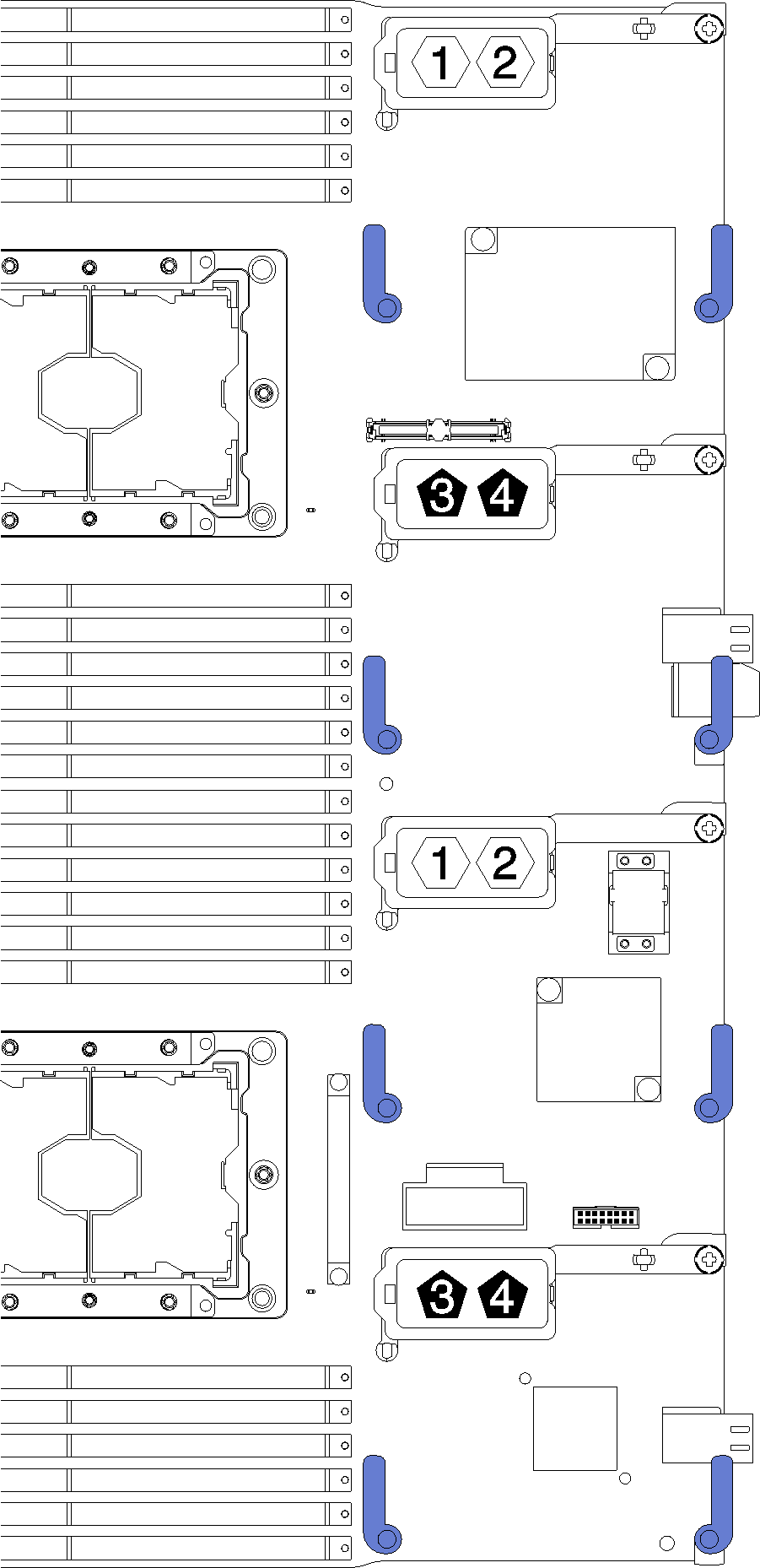
Figure 2. I/O expansion adapter
To install an I/O expansion adapter, complete the following steps:
Figure 3. I/O expansion adapter installation
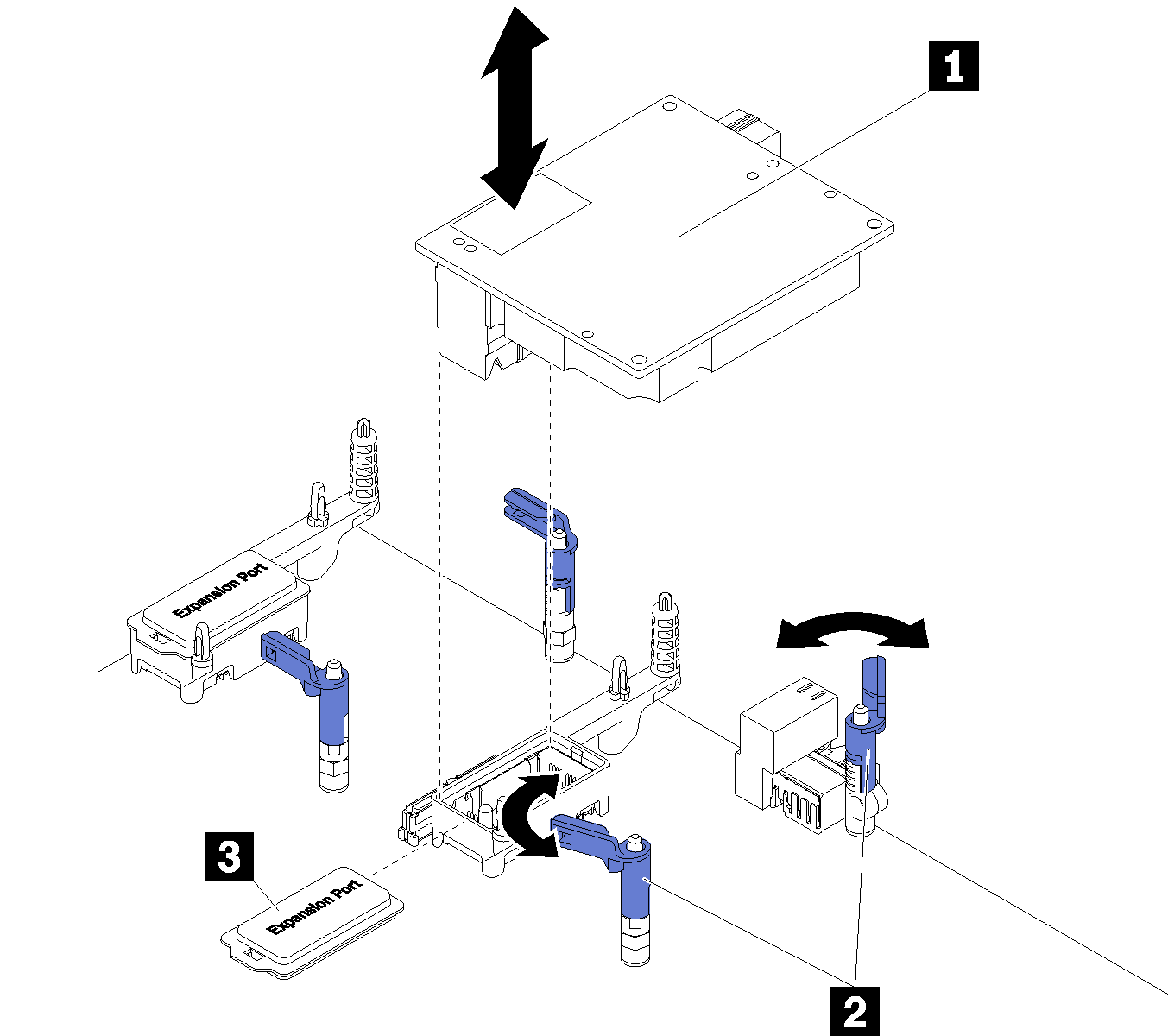
| 1 I/O expansion adapter | 3 Expansion cover |
| 2 Retention clips |
After you install the I/O expansion adapter, complete the following steps:
- See the documentation that comes with the I/O expansion adapter for device-driver and configuration information to complete the installation.
Demo video
Give documentation feedback