Install the system I/O board
Follow the instructions in this section to install the system I/O board.
About this task
This task must be operated by trained technicians that are certified by Lenovo Service. Do not attempt to remove or install the part without proper training and qualification.
Read Installation Guidelines and Safety inspection checklist to ensure that you work safely.
Power off the server and peripheral devices and disconnect the power cords and all external cables. See Power off the server.
Prevent exposure to static electricity, which might lead to system halt and loss of data, by keeping static-sensitive components in their static-protective packages until installation, and handling these devices with an electrostatic-discharge wrist strap or other grounding systems.
Procedure
- Install the system I/O board.Figure 1. System I/O board installation
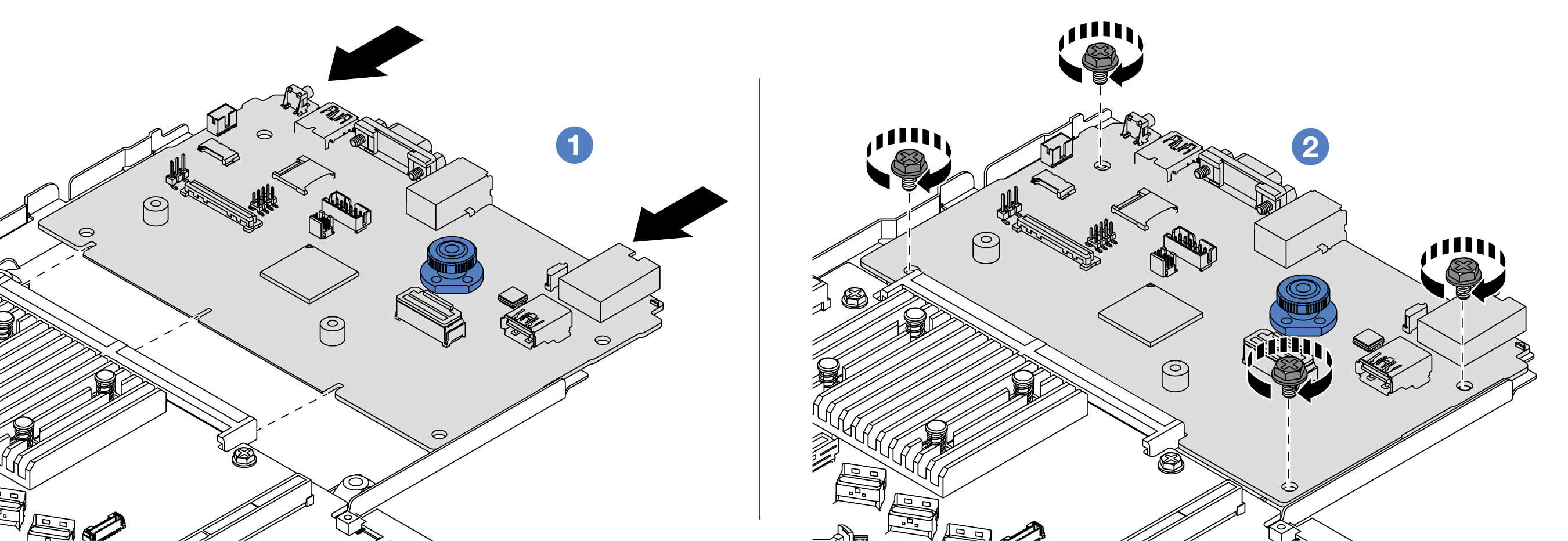
 Align the contacts on the system I/O board with the slots on the processor board, and use both hands to push the system I/O board and slightly insert it into the connector.NoteTo prevent the contacts of the system I/O board from damage, ensure that the system I/O board is aligned correctly with the connector on the processor board, and remains as horizontal as possible during the insertion.Figure 2. Install with both hands
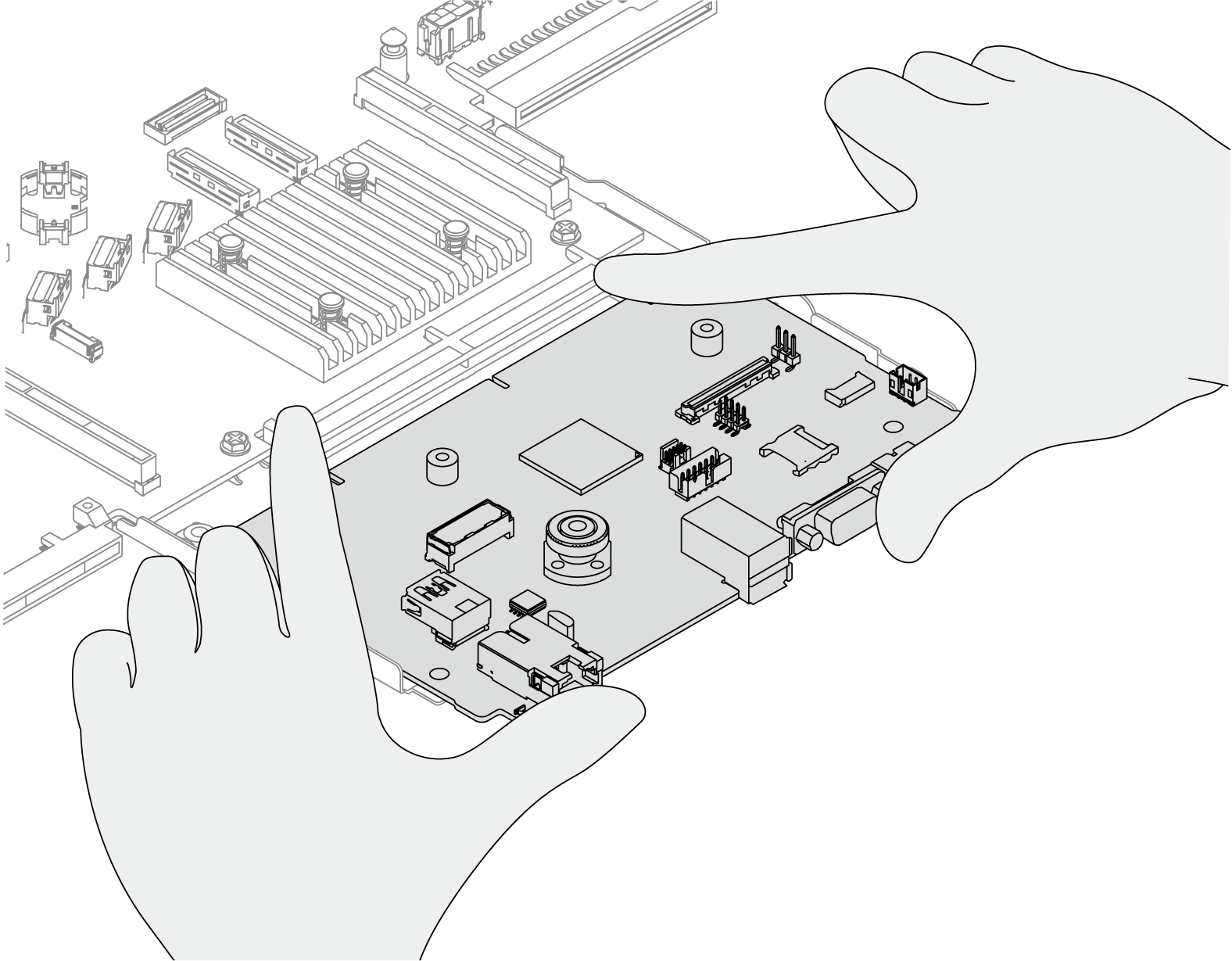
 Install the screws to install the system I/O board to the supporting metal sheet.
After you finish
- Install any components that you have removed before the removal of system I/O board.
Properly route and secure the cables in the server. Refer to detailed cable routing information for each component in Internal cable routing.
Install the rear drive cage if you have removed it. See Install the 2.5-inch rear drive assembly.
Install the air baffle if you have removed it. See Install the air baffle.
Install the top cover. See Install the top cover.
Push the power supplies into the bays until they click into place.
Connect power cords to the server and turn on the server.
Reset the UEFI password if you set the password before. See Reset the UEFI password.
Demo video