Rear view
The rear of the server provides access to several connectors and components, including the power supplies, PCIe adapters, hot-swap drive bays, serial port, and Ethernet connectors.
Rear view of server model with three PCIe slots
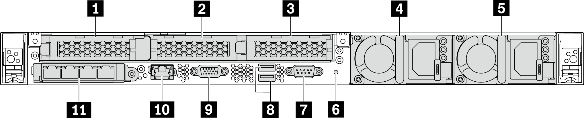
| 1 PCIe slot 1 on riser 1 assembly | 2 PCIe slot 2 on riser 2 assembly |
| 3 PCIe slot 3 on riser 2 assembly | 4 Power supply 1 |
| 5 Power supply 2 (optional) | 6 NMI button |
| 7 Serial port | 8 USB 3.2 Gen 1 (5 Gbps) connectors |
| 9 VGA connector | 10 RJ45 BMC management network connector |
| 11 Ethernet connectors on OCP 3.0 Ethernet adapter (optional, two or four connectors may be available) |
1 PCIe slot 1 on riser 1 assembly
Slot 1: PCIe x16, low-profile
Your server supports the following riser card configurations for riser 2 assembly:
Slot 2: PCIe x16 (x16, x8, x4, x1), low-profile
Slot 3: PCIe x16 (x16, x8, x4, x1), low-profile
Slot 2: no riser card installed
Slot 3: PCIe x16 (x16, x8, x4, x1), low-profile
Rear view of server model with two PCIe slots
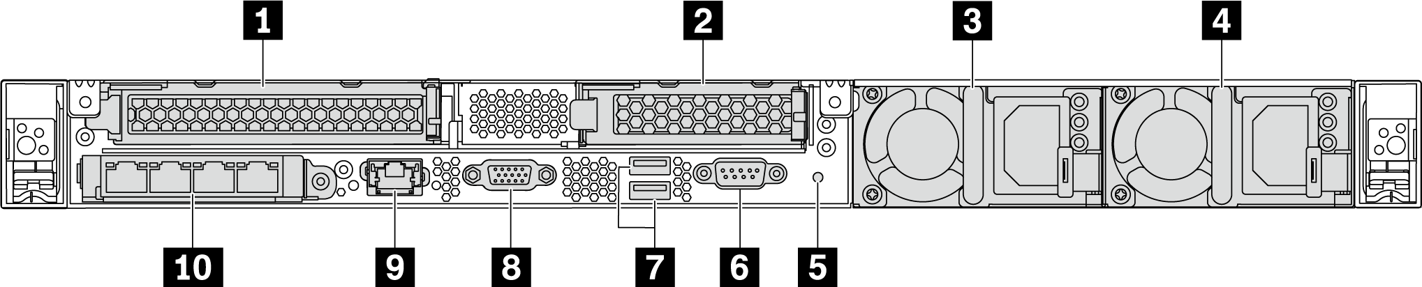
| 1 PCIe slot 1 on riser 1 assembly | 2 PCIe slot 3 on riser 2 assembly |
| 3 Power supply 1 | 4 Power supply 2 (optional) |
| 5 NMI button | 6 Serial port |
| 7 USB 3.2 Gen 1 (5 Gbps) connectors | 8 VGA connector |
| 9 BMC management network connector | 10 Ethernet connectors on OCP 3.0 Ethernet adapter (optional, two or four connectors may be available) |
1 PCIe slot 1 on riser 1 assembly
Your server supports the following riser card for riser 1 assembly:
Slot 1: PCIe x16 (x16, x8, x4, x1), full-height, full-length
2 PCIe slot 3 on riser 2 assembly
Your server supports the following riser card for riser 2 assembly:
Slot 3: PCIe x16 (x16, x8, x4, x1), low-profile
Rear view of server model with two hot-swap drive bays and one PCIe slot
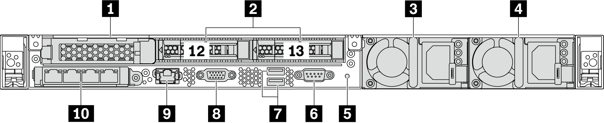
| 1 PCIe slot 1 | 2 Rear 2.5-inch drive bays |
| 3 Power supply 1 | 4 Power supply 2 (optional) |
| 5 NMI button | 6 Serial port |
| 7 USB 3.2 Gen 1 (5 Gbps) connectors | 8 VGA connector |
| 9 BMC management network connector | 10 Ethernet connectors on OCP 3.0 Ethernet adapter (optional, two or four connectors may be available) |
Slot 1: PCIe x16 (x16, x8, x4, x1), low-profile
2 Rear 2.5-inch drive bays
Used to install two 2.5-inch hot-swap drives on the rear of the server.
The number of the installed drives in your server varies by model. When you install drives, follow the order of the drive bay numbers.
The EMI integrity and cooling of the server are protected by having all drive bays occupied. The vacant drive bays must be occupied by drive bay fillers or drive fillers.
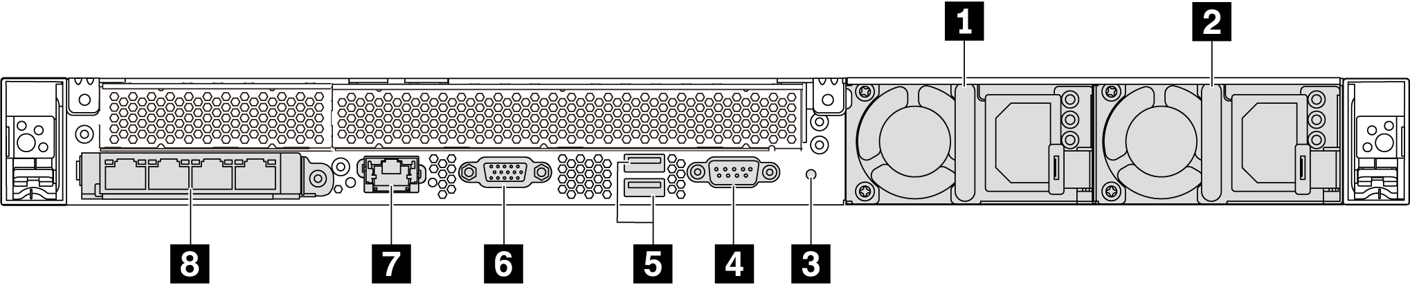
Rear view of server model with one PCIe slot
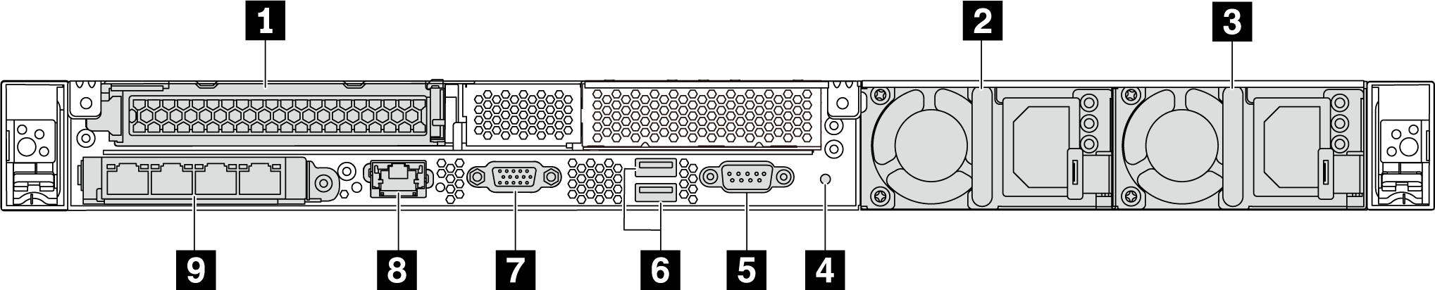
| 1 PCIe slot 1 on riser 1 assembly | 2 Power supply 1 |
| 3 Power supply 2 (optional) | 4 NMI button |
| 5 Serial port | 6 USB 3.2 Gen 1 (5 Gbps) connectors |
| 7 VGA connector | 8 BMC management Ethernet connector |
| 9 Ethernet connectors on OCP 3.0 Ethernet adapter (optional, two or four connectors may be available) |
Slot 1: PCIe x16 (x16, x8, x4, x1), full-height/full-length
Rear view of server model with no PCIe slot
| 1 Power supply 1 | 2 Power supply 2 (optional) |
| 3 NMI button | 4 Serial port |
| 5 USB 3.2 Gen 1 (5 Gbps) connectors | 6 VGA connector |
| 7 BMC management network connector | 8 Ethernet connectors on OCP 3.0 Ethernet adapter (optional, two or four connectors may be available) |
Power supply 1
Power supply 2 (optional)
The hot-swap redundant power supplies help you avoid significant interruption to the operation of the system when a power supply fails. You can purchase a power supply option from Lenovo and install the power supply to provide power redundancy without turning off the server.
On each power supply, there are three status LEDs near the power cord connector. For information about the LEDs, see Rear view LEDs.
NMI button
Press this button to force a nonmaskable interrupt (NMI) to the processor. By this way, you can make the operating system halt (such as Windows Blue Screen of Death) and take a memory dump. You might have to use a pen or the end of a straightened paper clip to press the button.
Serial port
Used to connect to the host system serial interface.
USB 3.2 Gen 1 (5 Gbps) connectors (2)
Used to attach a device that requires a USB 2.0 or 3.1 connection, such as a USB keyboard, USB mouse, or USB storage device.
VGA connector
Used to attach a high-performance monitor, a direct-drive monitor, or other devices that use a VGA connector.
BMC management network connector
Used to attach an Ethernet cable to manage the baseboard management controller (BMC).
Ethernet connectors on OCP 3.0 Ethernet adapter (optional)
Figure 6. OCP module (two connectors)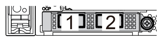 Figure 7. OCP module (four connectors)
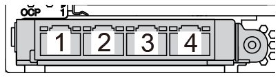 Note
NoteThe OCP 3.0 Ethernet adapter provides two or four extra Ethernet connectors for network connections.
Any of the connectors (connector 1 by default) on the OCP module can function as a shared management connector.