See this section to understand the cable routing of 10 front 2.5'' SAS/SATA drives with the 10 x 2.5'' AnyBay backplane (Gen 4) installed.
The following illustrations and tables show the mapping relationship between backplane connectors and system board assembly connectors for onboard configuration.
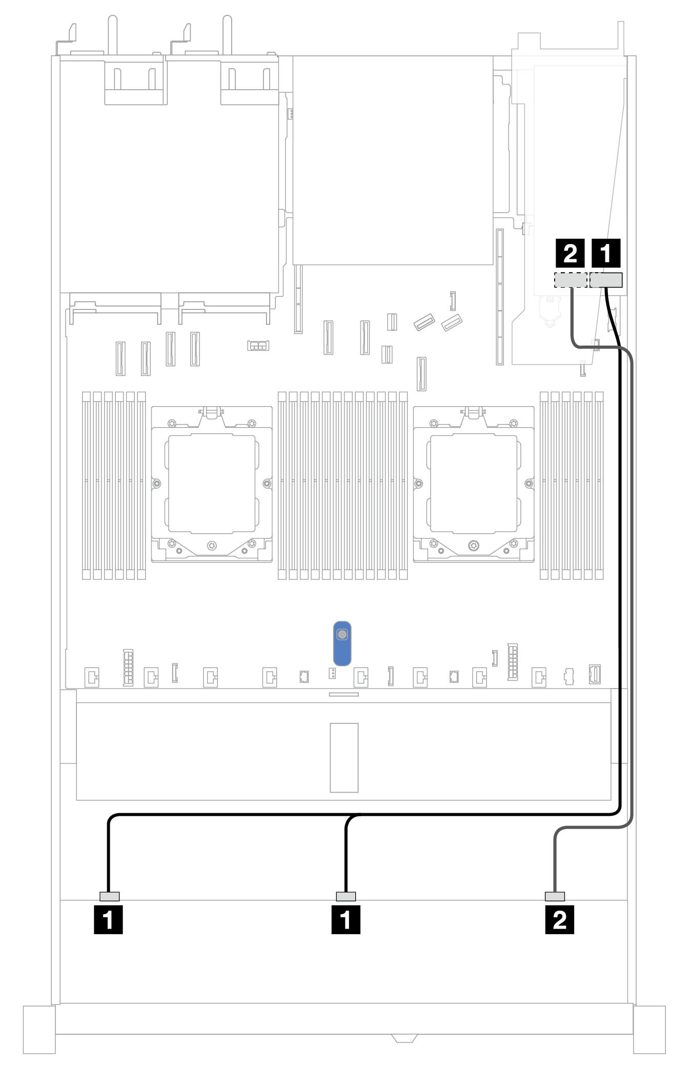
Figure 1. Cable routing for onboard configuration of 10 x 2.5 SAS/SATA front drives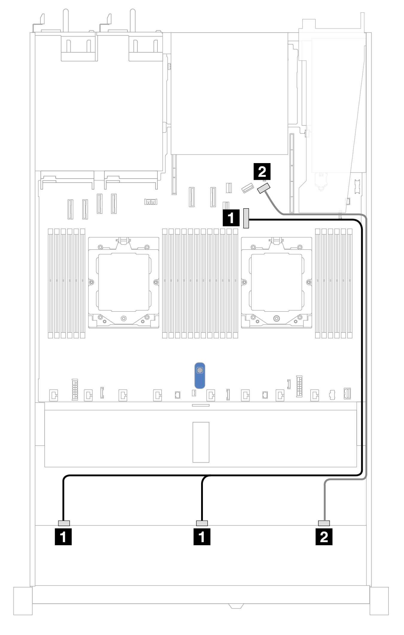
Table 1. Mapping between one front AnyBay backplane and system board for onboard configuration| Backplane | From | To |
|---|
| Front BP (SAS) | 1 SAS 0, SAS 1 | 1 PCIe connector 7 |
| 2 SAS 2 | 2 PCIe connector 9 |
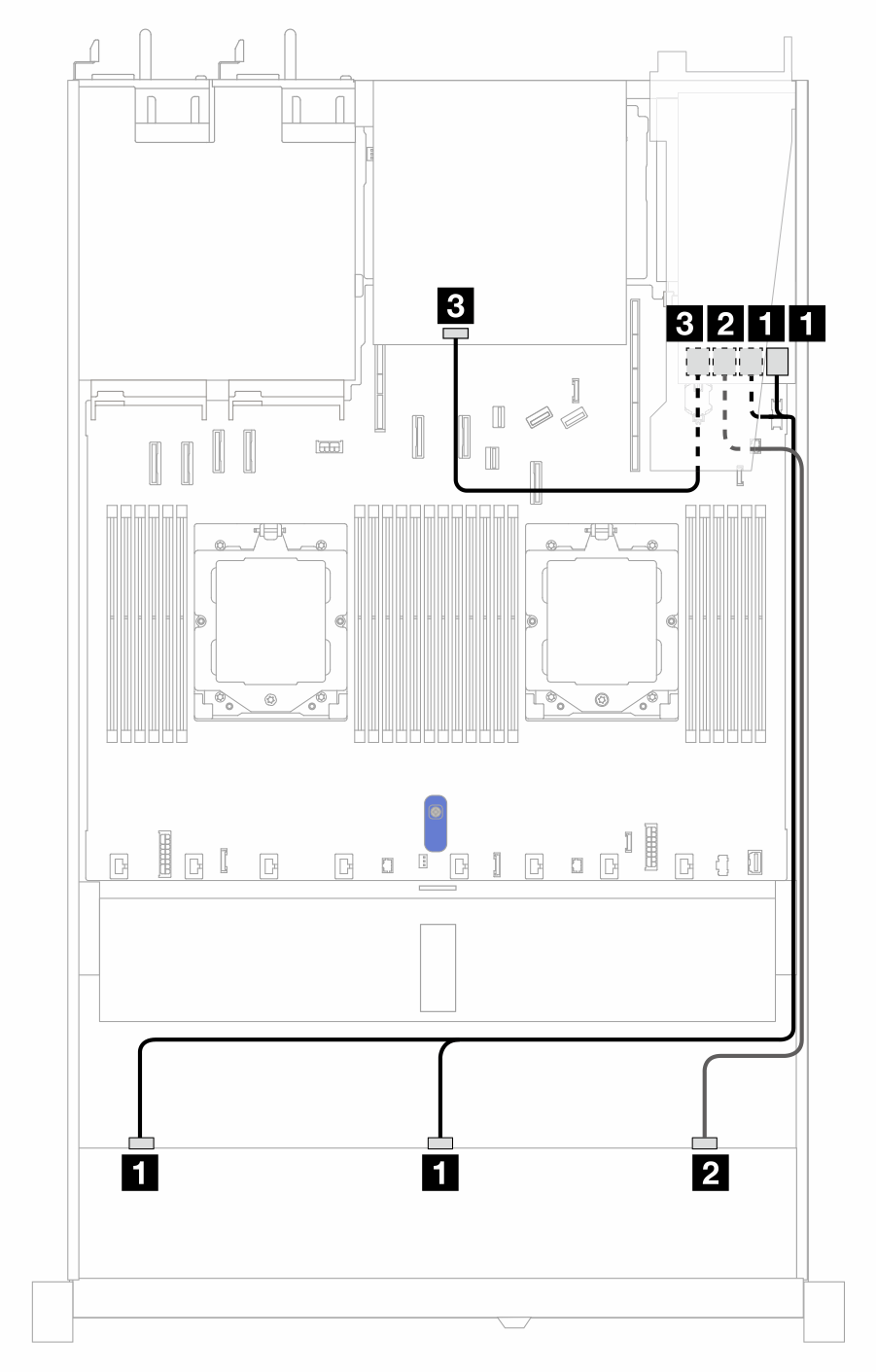
Figure 2. Cable routing for onboard configuration of 10 x 2.5'' SAS/SATA front drives and 2 x 2.5'' SAS/SATA or 2 x 7mm drive rear drives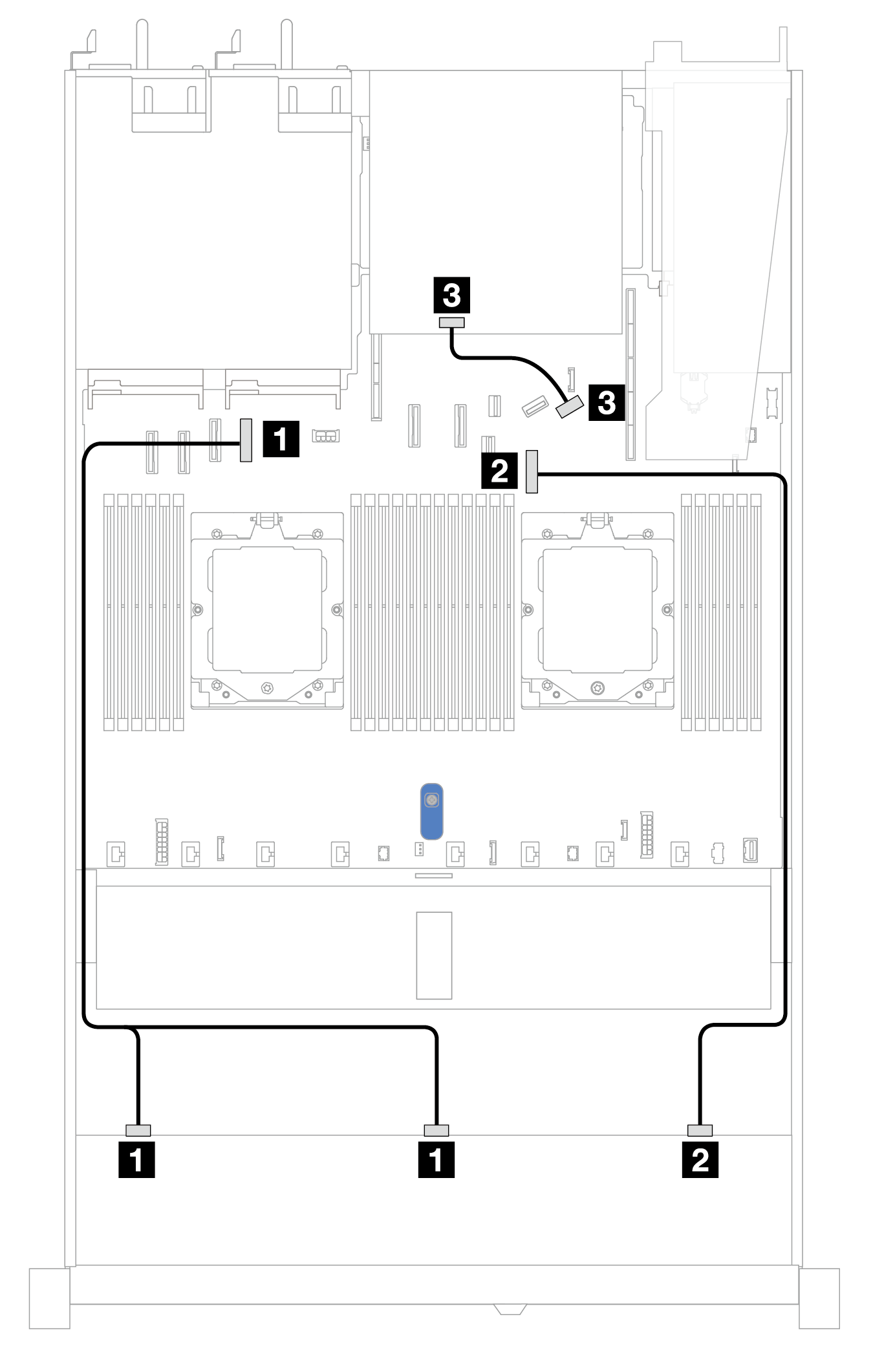
Table 2. Mapping between one front AnyBay and one rear SAS/SATA backplanes and processor board for onboard configuration| Backplane | From | To |
|---|
| Front BP (SAS) | 1 SAS 0, SAS 1 | 1 PCIe connector 4 |
| 2 SAS 2 | 2 PCIe connector 7 |
| Rear BP (SAS) | 3 SAS | 3 PCIe connector 9 |
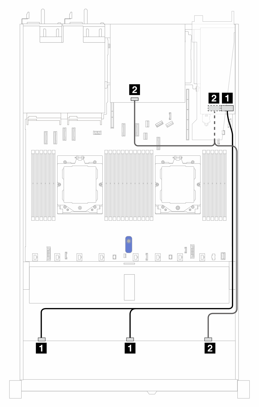
Figure 3. Cable routing for onboard configuration of 10 x 2.5'' SAS/SATA front drives and 2 x 2.5'' NVMe rear drives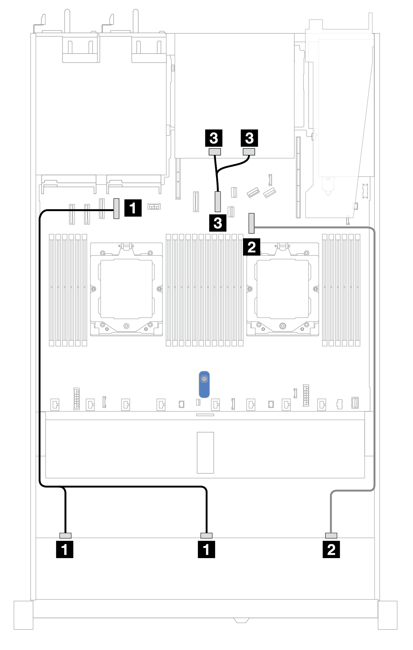
Table 3. Mapping between one front AnyBay and one rear NVMe backplanes and system board assembly for onboard configuration| Backplane | From | To |
|---|
| Front BP (SAS) | 1 SAS 0, SAS 1 | 1 PCIe connector 4 |
| 2 SAS 2 | 2 PCIe connector 7 |
| Rear BP (SAS) | 3 NVMe 0, NVMe 1 | 3 PCIe connector 6 |
The following tables show the mapping relationship between backplane connectors and a CFF RAID adapter.
The following illustrations are for Gen 4 adapters. For Gen 3 adapters, the illustration might be slightly different.
Figure 7. Cable routing for 10 front 2.5'' SAS/SATA drives bays with a 16i CFF RAID adapter (Gen 3 or Gen 4) 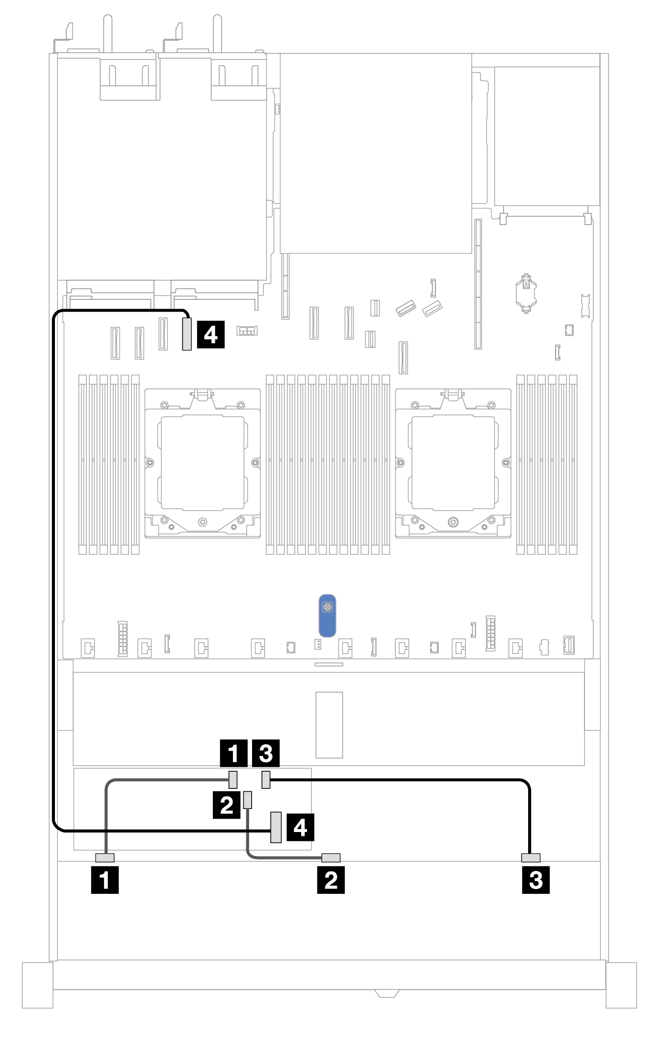
Table 7. Mapping between one front AnyBay and a CFF RAID adapter| Backplane | From | To |
|---|
| Front BP (SAS) | 1 SAS 0 | 1 C0 |
| 2 SAS 1 | 2 C1 |
| 3 SAS 2 | 3 C2 |
| CFF RAID adapter | 4 MB input | 4 PCIe connector 4 |
Figure 8. Cable routing for 10 front 2.5'' SAS/SATA drives bays and a 16i CFF RAID adapter (Gen 3 or Gen 4) with 2 x 2.5'' rear SAS/SATA drives installed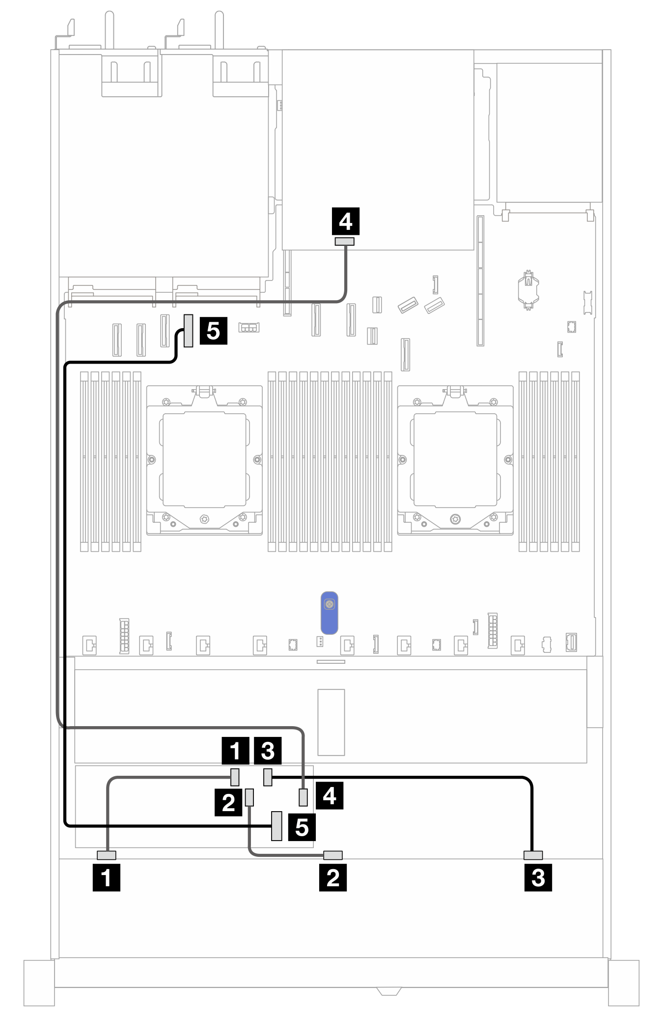
Table 8. Mapping between one front AnyBay and one rear NVMe backplane and a CFF RAID adapter| Backplane/adapter | From | To |
|---|
| Front BP (SAS) | 1 SAS 0 | 1 C0 |
| 2 SAS 1 | 2 C1 |
| 3 SAS 2 | 3 C2 |
| Rear BP (SAS) | 4 SAS | 3 C3 |
| CFF RAID adapter | 5 MB input | 5 PCIe connector 4 |