16-EDSFF drive backplane
Use this section to understand the backplane cable routing for server model with 16 E1.S EDSFF front drives.
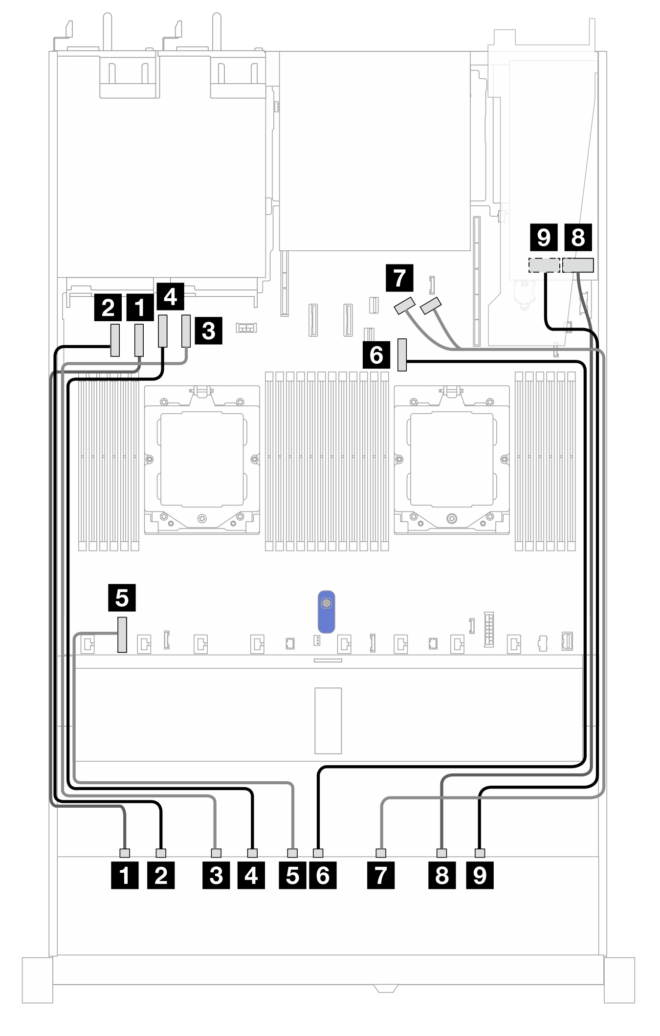
Cable routing with a re-timer adapter
The following table shows the mapping relationship between backplane, re-timer adapter and system board connectors.
| From | To |
|---|---|
| 1 EDSFF 0–1 | 1 PCIe connector 2 |
| 2 EDSFF 2–3 | 2 PCIe connector 1 |
| 3 EDSFF 4–5 | 3 PCIe connector 4 |
| 4 EDSFF 6–7 | 4 PCIe connector 3 |
| 5 Power | 5 Backplane power connector on the system board |
| 6 EDSFF 8–9 | 6 PCIe connector 7 |
| 7 EDSFF 10–11 | 7 PCIe connector 8 and 9 |
| 8 EDSFF 12–13 | 8 C0 |
| 9 EDSFF 14–15 | 9 C1 |
Give documentation feedback