
Remove the front I/O module

Use this information to remove the front I/O module.

About this task

Depending on the server model, the server might come with one of the following front operator panels:

Front I/O module without LCD display

1 Front operator panel without an LCD display

Front I/O module with LCD display

1 Front operator panel with an LCD display (called integrated diagnostics panel)
Attention
  • Read Installation Guidelines and Safety inspection checklist to ensure that you work safely.

  • Power off the server and peripheral devices and disconnect the power cords and all external cables. See Power off the server.

  • Prevent exposure to static electricity, which might lead to system halt and loss of data, by keeping static-sensitive components in their static-protective packages until installation, and handling these devices with an electrostatic-discharge wrist strap or other grounding system.

Procedure

  1. Make preparation for the task.
    1. If the security bezel is installed, remove it. See Remove the security bezel.
    2. If the server is installed in a rack, slide the server out on its rack slide rails to gain access to the top cover, or remove the server from the rack. See Remove the server from rack.
    3. Remove the top cover. See Remove the top cover.
    4. Remove the air baffle. See Remove the air baffle.
  2. Disconnect the cables of the front I/O module from the system board assembly.
    Note
    • If you need to disconnect cables from the system board assembly, disengage all latches or release tabs on cable connectors first. Failing to release the tab before removing the cables will damage the cable sockets on the system board assembly. Any damage to the cable sockets might require replacing the system board assembly.

    • The connectors on your system board assembly might look different from those in the illustration, but the removal procedure is the same.

      1. Press the release tab to release the connector.

      2. Disengage the connector from the cable socket.

    Figure 1. Disconnecting cables from the system board assembly
    Disconnecting the external diagnostics cable or front panel cable


    Disconnecting the USB cable

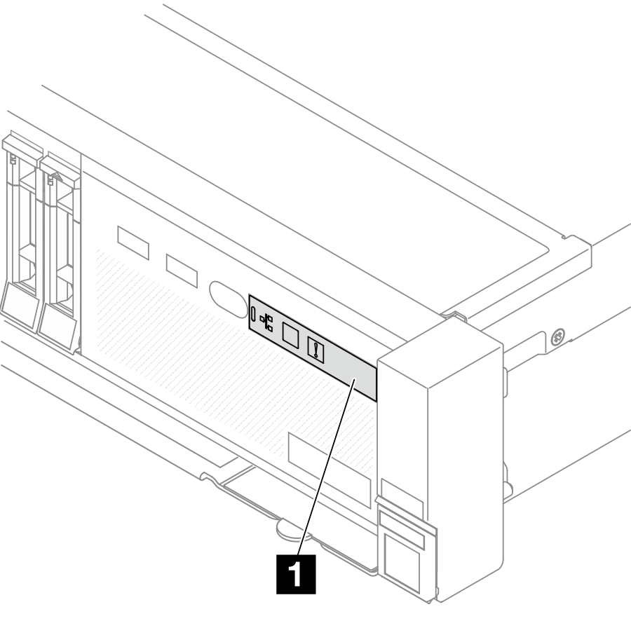
  3. Remove the front I/O module from the front chassis.
    Figure 2. Front I/O module without the LCD display
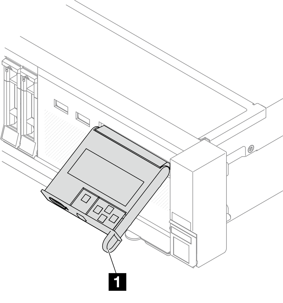
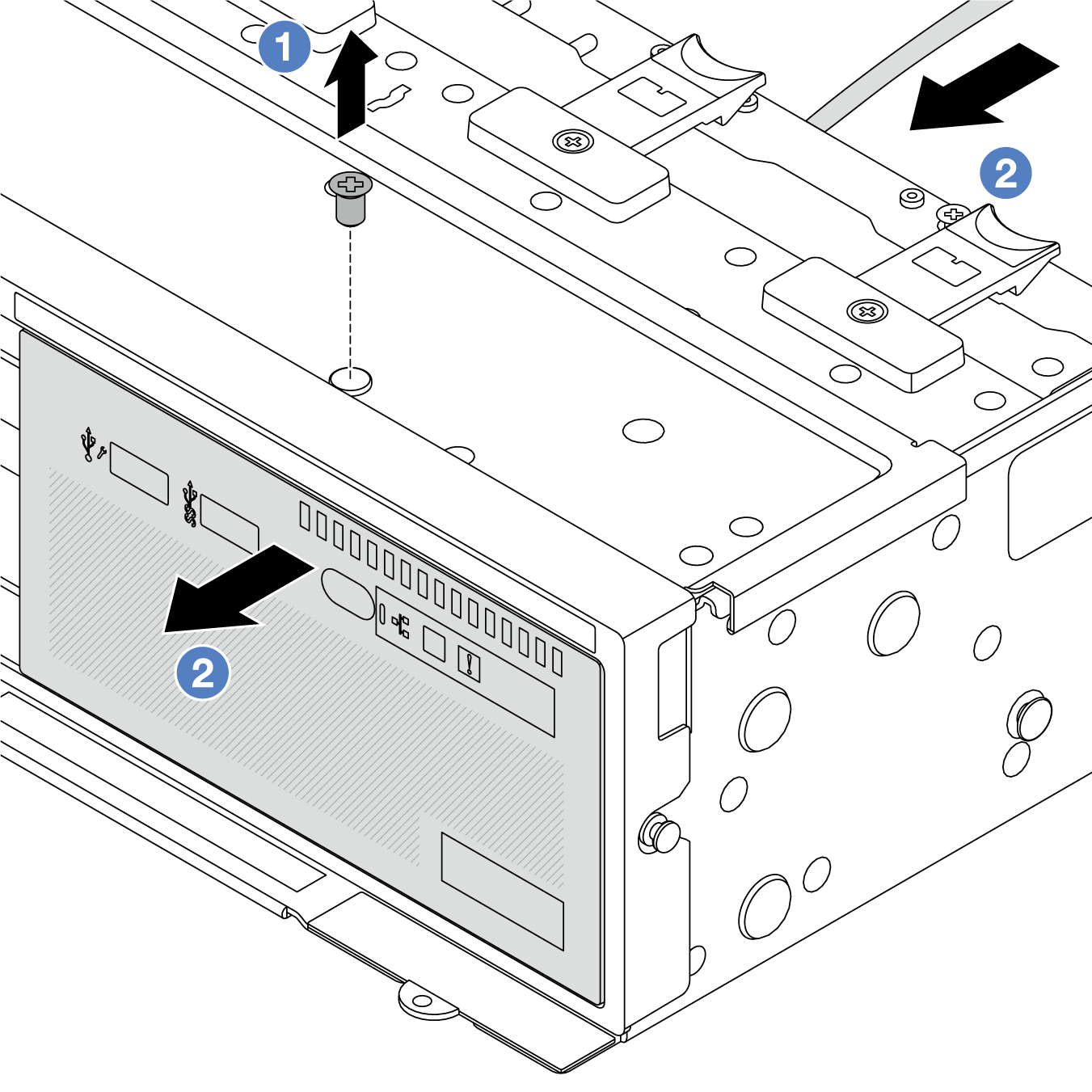
    Front I/O module without an LCD display
    Figure 3. Front I/O module with the LCD display (integrated diagnostics panel)
    Front I/O module with the integrated diagnostics panel
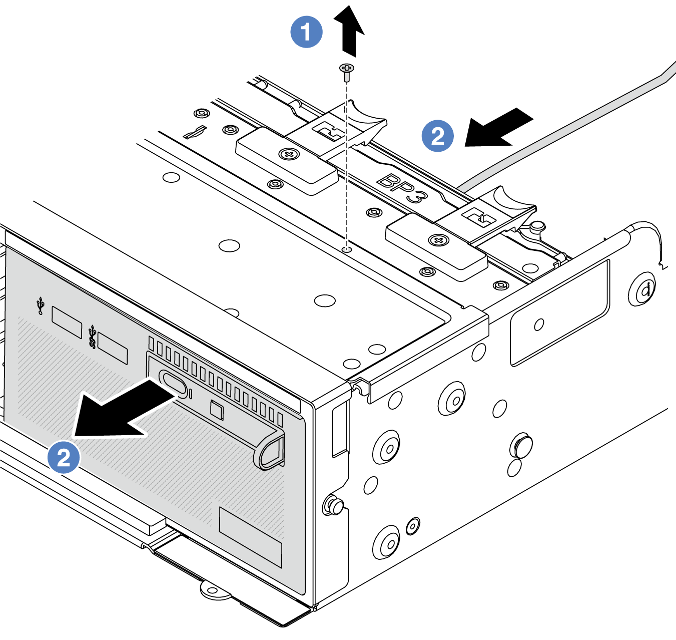
    1. Remove the screw that secures the front I/O module.
    2. Slide the media bay out of the front chassis.
  4. (Optional) If you are replacing the integrated diagnostics panel, remove the diagnostics panel from the front I/O module.
    Figure 4. Diagnostics panel removal
    Diagnostics panel removal
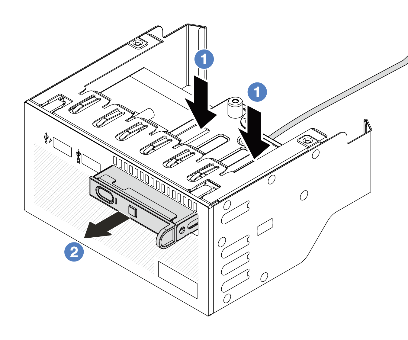
    1. Press down the clips as shown.
    2. Pull the diagnostics panel by its handle to get it out of its assembly.

After you finish

If you are instructed to return the component or optional device, follow all packaging instructions, and use any packaging materials for shipping that are supplied to you.

Demo video

Watch the procedure on YouTube