System-board-assembly LEDs
The following illustrations show the light-emitting diodes (LEDs) on the system board assembly.
Processor-board LEDs
Figure 1. LEDs on the processor board 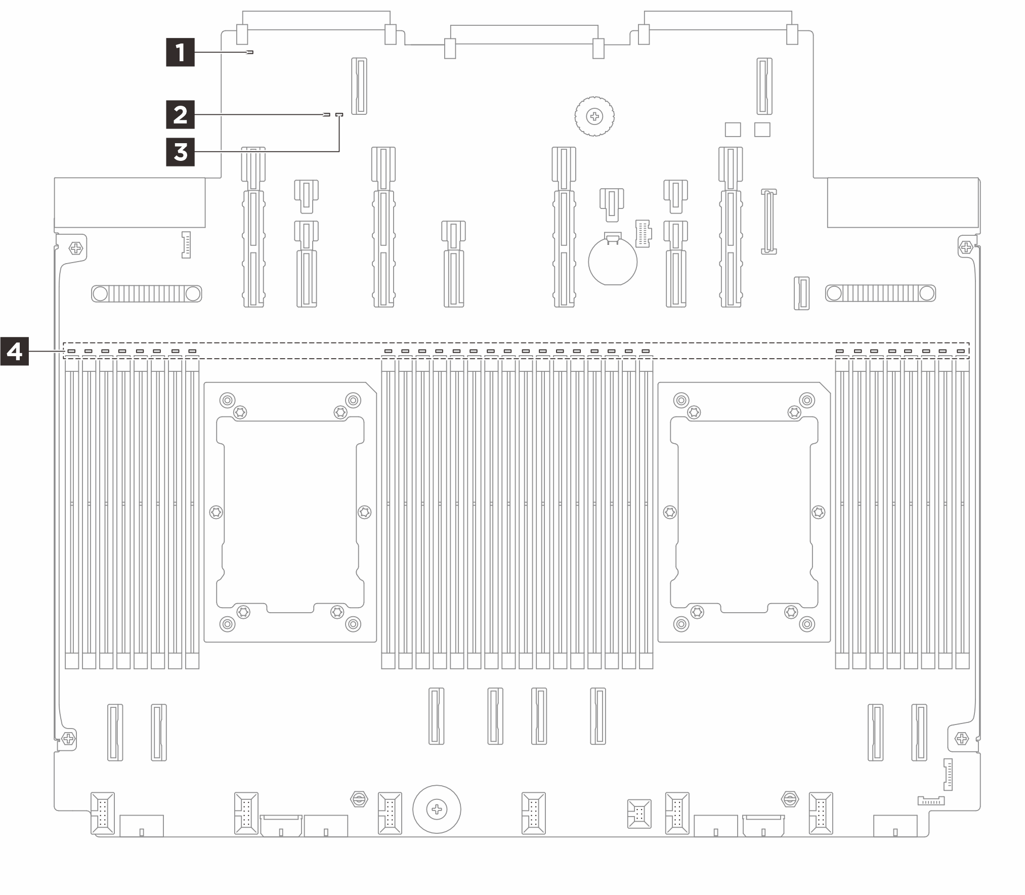 | 4 DIMM error LEDs (amber) Note Depending on the model, the processor board may not be equipped with the DIMM error LEDs. 5 PCIe error LEDs (amber) Note The PCIe error LEDs are designed specifically for the cable riser card. |
1 System error LED (yellow) | |
|---|---|
| Description | When this yellow LED is lit, another one or more LEDs in the server might also be lit to direct you to the error source. |
| Action | Check system logs or internal error LEDs to identify the failed part. For more information, see Front-operator-panel LEDs and buttons. |
2 System status LED (green) | |
|---|---|
| Description | The system status LED indicates the working status of the system.
|
| Action |
|
3 FPGA heartbeat LED (green) | |
|---|---|
| Description | The FPGA heartbeat LED helps you identify the FPGA status.
|
| Action | If FPGA heartbeat LED is always off or always on, do the following:
|
4 DIMM error LEDs (amber) | |
|---|---|
| Description | When a memory module error LED is lit, it indicates that the corresponding memory module has failed. |
| Action | For more information, see Memory problems. |
5 PCIe error LEDs (amber) | |
|---|---|
| Description | When a PCIe error LED is lit, it indicates that the corresponding PCIe signal cable of the cable riser card is incorrectly connected. |
| Action | Check the system log, and connect the PCIe signal cable to the correct connector following the log. |
System I/O board LEDs
Figure 2. LEDs on the system I/O board (DC-SCM) 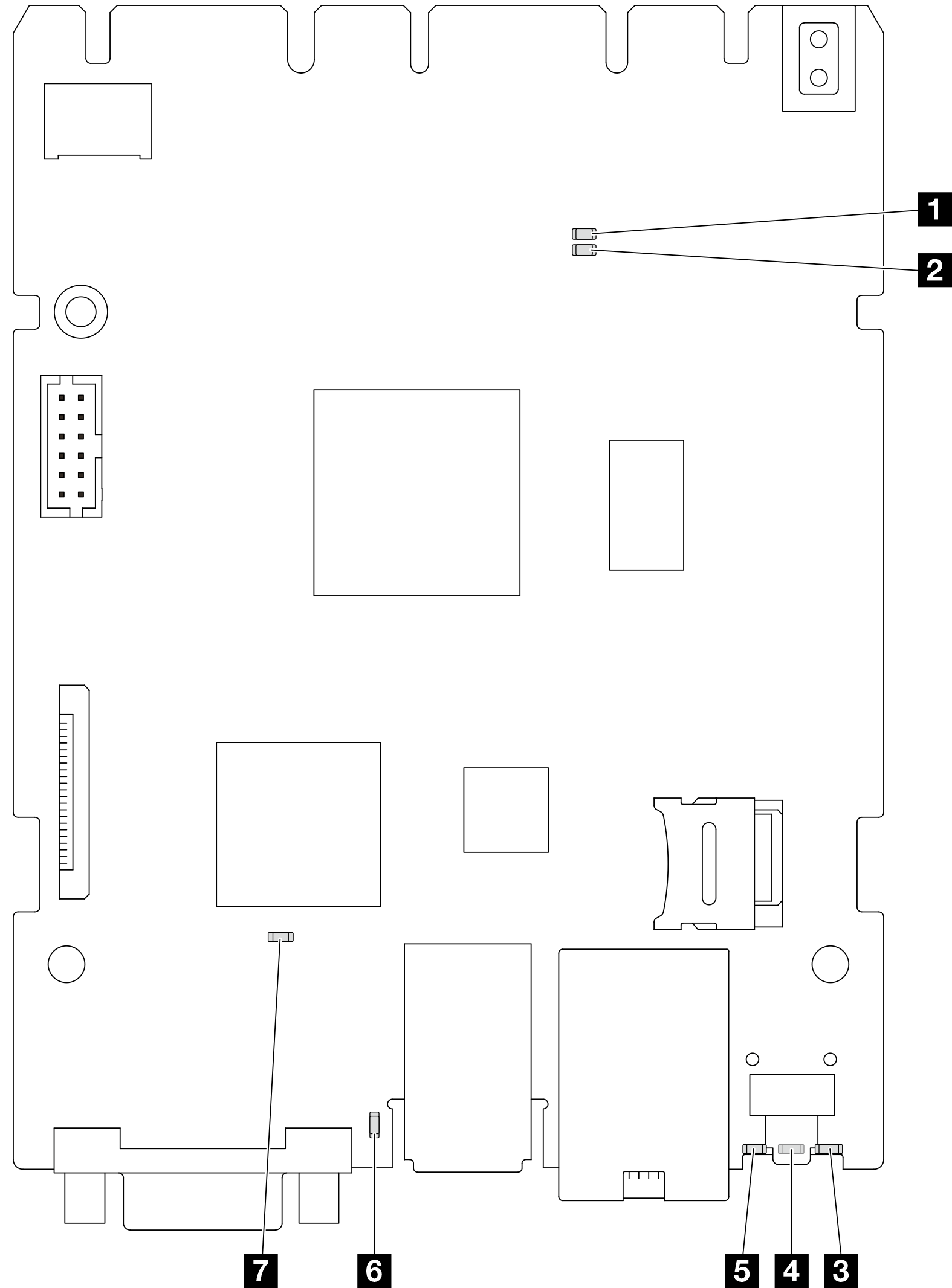 |
| Scenario | 1 AP0 LED | 2 AP1 LED | 3 RoT fault LED | 7 SCM FPGA heartbeat LED | 6 XCC heartbeat LED | Actions |
|---|---|---|---|---|---|---|
| RoT security module fatal firmware failure | Off | Off | On | N/A | N/A | Replace the system I/O board. |
| Blink | N/A | On | N/A | N/A | Replace the system I/O board. | |
| No system power (FPGA heartbeat LED off) | Off | Off | Off | Off | Off | If the AC power is on, but the system board assembly does not have power, then:
|
| XCC firmware recoverable error | Blink | N/A | Off | N/A | N/A | Information only. No action is required. |
| XCC firmware is recovered from error | Blink | N/A | Off | N/A | N/A | Information only. No action is required. |
| UEFI firmware authentication failure | N/A | Blink | Off | N/A | N/A | Information only. No action is required. |
| UEFI firmware is recovered from authentication failure | N/A | On | Off | N/A | N/A | Information only. No action is required. |
| System is OK (FPGA heartbeat LED is On) | On | On | Off | On | Blink (1 Hz) | Information only. No action is required. |
4 System error LED (yellow) | |
|---|---|
| Description | When this yellow LED is lit, another one or more LEDs in the server might also be lit to direct you to the error source. |
| Action | Check system logs or internal error LEDs to identify the failed part. For more information, see Front-operator-panel LEDs and buttons. |
5 System ID LED (blue) | |
|---|---|
| Description | The front system ID LED helps you locate the server. |
| Action | Each time you press the system ID button, the state of both system ID LEDs changes, and the state can be on, blinking, or off. |
6 XCC heartbeat LED (green) | |
|---|---|
| Description | The XCC heartbeat LED helps you identify the XCC status.
|
| Action |
|