3-slot PCIe expansion cage 1 cable routing
Use the section to understand the cable routing for 3-slot PCIe expansion cage 1.
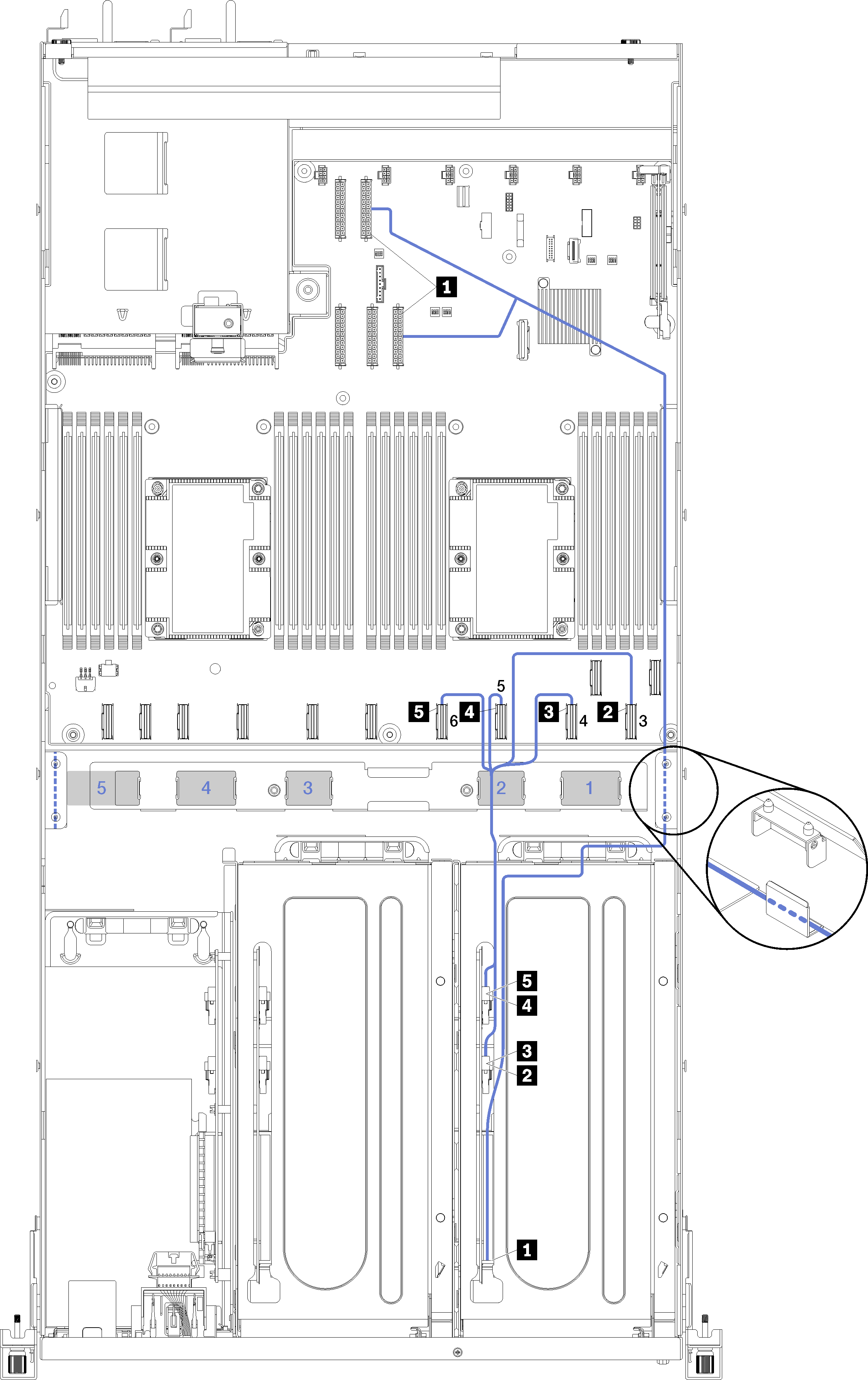
The PCIe expansion cage power cable is routed through the right cable routing trough (as you are looking from the front of the server). The order of cable placement for cables in the right cable routing trough is as follows:
PCIe 13 cable
USB cable
VGA cable
PCIe expansion cage 1 power cable assembly
Fan cage power cable. See Fan cage cable routing for system fan cage routing information.
| Cable | From | To |
|---|---|---|
| 1 PCIe expansion cage 1 power cable (includes cabling for the PCIe expansion cage 1 and both GPU adapters) | Power connector 1 and power connector 3 on the system board. | Note The GPU adapter power cable is routed through the right cable routing trough (as you are looking from the front of the server).
|
| 2 PCIe 3 cable | PCIe connector 3 on the system board. | To PCIe connector F on the PCIe expansion cage 1 expansion card through cable pathway 2. |
| 3 PCIe 4 cable | PCIe connector 4 on the system board. | To PCIe connector E on the PCIe expansion cage 1 expansion card through cable pathway 2. |
| 4 PCIe 5 cable | PCIe connector 5 on the system board. | To PCIe connector A on the PCIe expansion cage 1 expansion card through cable pathway 2. |
| 5 PCIe 6 cable | PCIe connector 6 on the system board. | To PCIe connector B on the PCIe expansion cage 1 expansion card through cable pathway 2. |