Remove the front I/O expansion board carrier
Follow instructions in this section to remove the front I/O expansion board carrier.
About this task
Attention
- Read Installation Guidelines and Safety inspection checklist to ensure that you work safely.
- Power off the server and peripheral devices and disconnect the power cords and all external cables. See Power off the server.
- If the server is installed in a rack, slide the server out on its rack slide rails to gain access to the top cover, or remove the server from the rack. See Remove the server from rack.
Procedure
- Make preparation for this task.
- Unfasten the two cable ties on the front drive tray to release the cables.Figure 1. Unfastening the cable ties
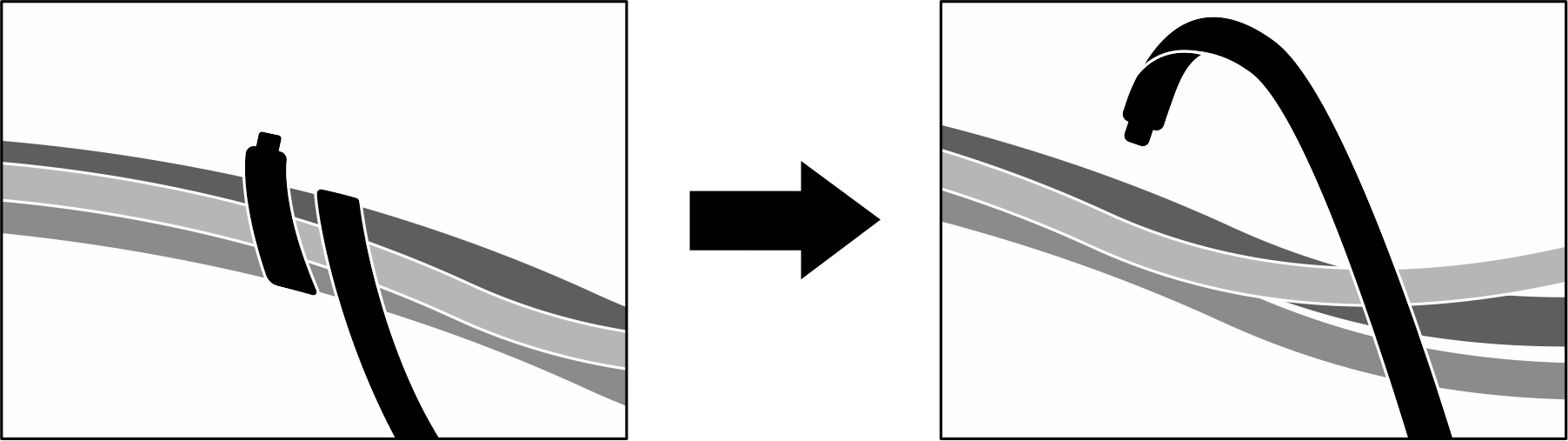
- Unfasten the two cable ties on the front drive tray to release the cables.
- Remove the radiator bracket.
 Unfasten the four screws that secure the radiator bracket to the chassis.
 Lift the radiator bracket out of the chassis.Figure 2. Radiator bracket removal
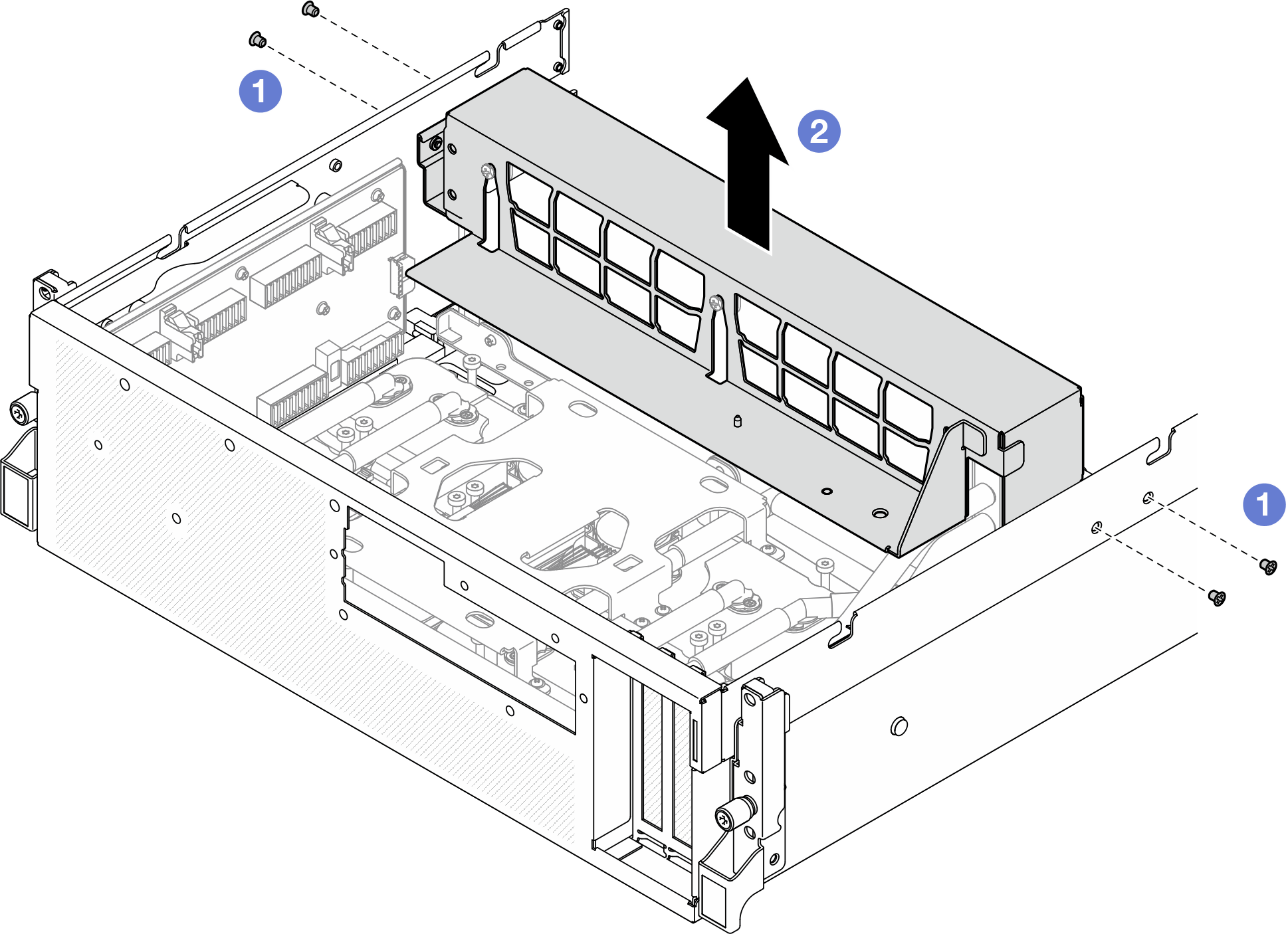
- Remove the front I/O expansion board carrier.
- Loosen the thumbscrew that secures the front I/O expansion board carrier to the chassis.
- Lift the plunger and slide the front I/O expansion board carrier toward the rear of the server to disengage the carrier from the guide pins; then, remove the carrier out of the chassis.Figure 3. Front I/O expansion board carrier removal
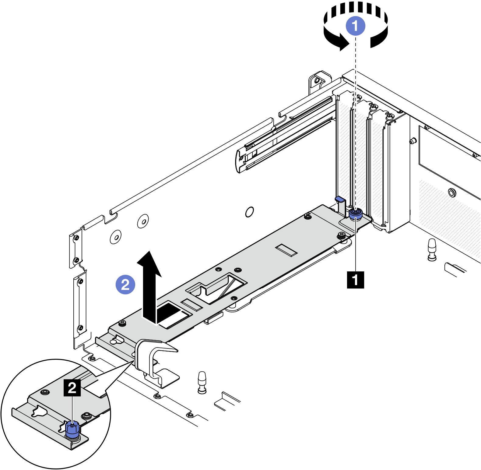
1 Thumbscrew 2 Plunger
After you finish
If you are instructed to return the component or optional device, follow all packaging instructions, and use any packaging materials for shipping that are supplied to you.
Demo video
Give documentation feedback