Install the front I/O expansion board carrier
Follow instructions in this section to install the front I/O expansion board carrier.
About this task
Attention
- Read Installation Guidelines and Safety inspection checklist to ensure that you work safely.
- Touch the static-protective package that contains the component to any unpainted metal surface on the server; then, remove it from the package and place it on a static-protective surface.
Procedure
 Align the front I/O expansion board carrier with the four guide pins on the chassis and lower the carrier into the chassis; then, slide the carrier toward the front of the server until the guide pins are fully seated in the guide holes on the carrier.
 Fasten the thumbscrew to secure the front I/O expansion board carrier to the chassis.Figure 1. Front I/O expansion board carrier installation
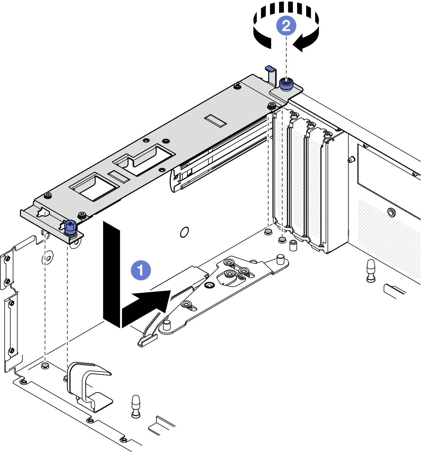
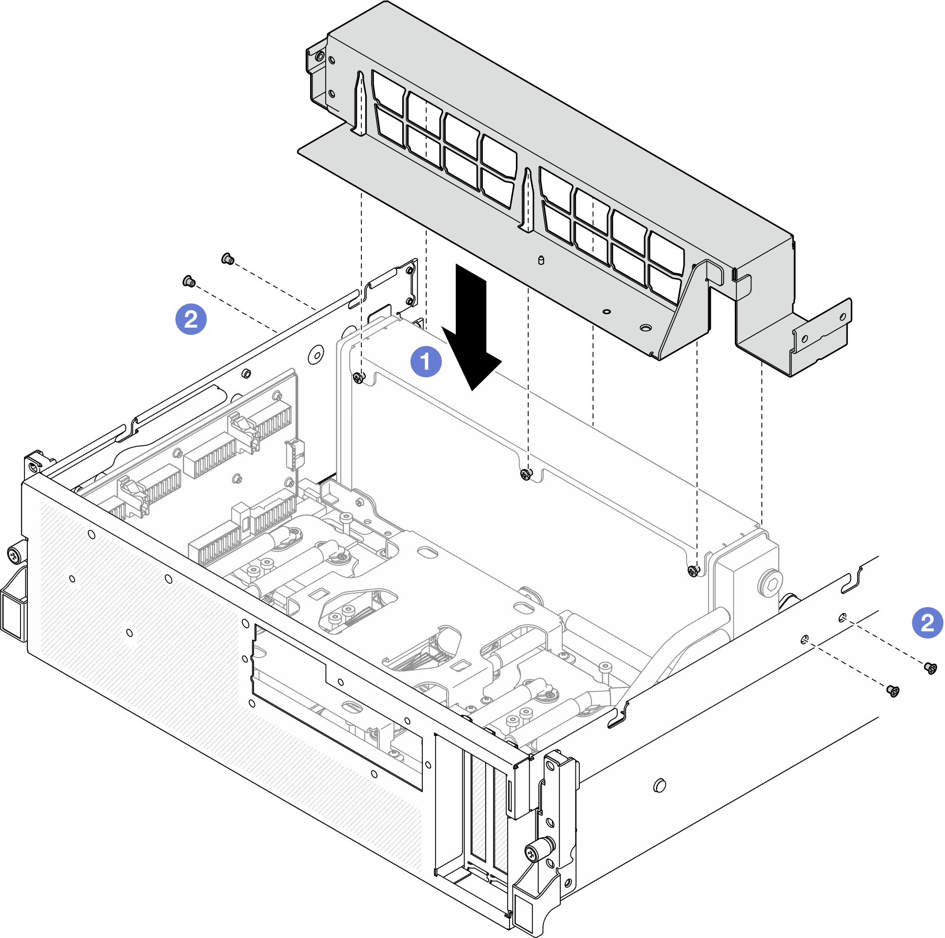
- Install the radiator bracket.
- Gently place the radiator bracket onto the radiator.
- Fasten the four screws to secure the radiator bracket to the chassis.Figure 2. Radiator bracket installation
After you finish
- Reinstall the front drive tray. See Install the front drive tray.
- Reinstall the CX-7 assembly. See Install the CX-7 assembly.
- Depending on the configuration, reinstall the 2.5-inch drive cage or the E3.S drive cage assembly. See Install the 2.5-inch drive cage or Install the E3.S drive cage assembly.
- Depending on the configuration, reconnect the power and signal cables to the 2.5-inch drive backplane or the E3.S dive backplane. See 2.5-inch drive backplane cable routing or E3.S drive backplane cable routing for more information.
- Depending on the configuration, reinstall the 2.5-inch hot-swap drives and the drive bay fillers (if any) or E3.S hot-swap drives and the drive bay fillers (if any). See Install a 2.5-inch hot-swap drive or Install an E3.S hot-swap drive
- Reconnect the following cables to the system board assembly.
- Front I/O module cables
- Front operator panel cable
- Reinstall the OSFP port card. See Install the OSFP port card.
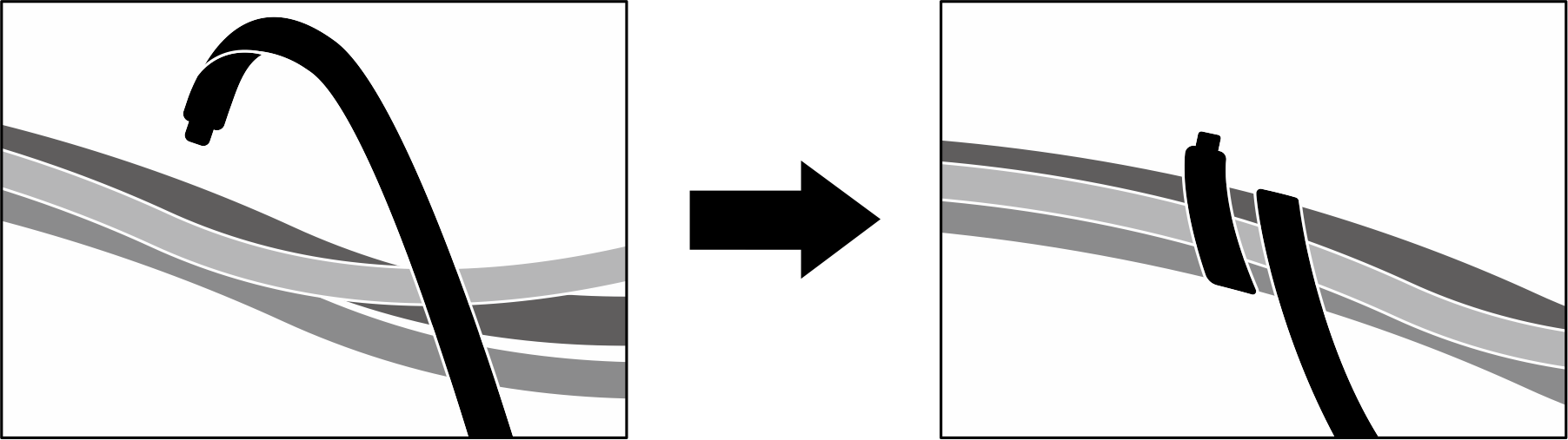
- Equally divide the cables that go through the right side of the front drive tray into two bundles, and secure them with the two cable ties.Figure 3. Securing cables with cable ties
- Reinstall the fan cage. See Install the fan cage.
- Reinstall the fans. See Install a fan.
- Complete the parts replacement. See Complete the parts replacement.
Demo video
Give documentation feedback