Front LEDs
This topic provides information about LEDs on the front of the server.
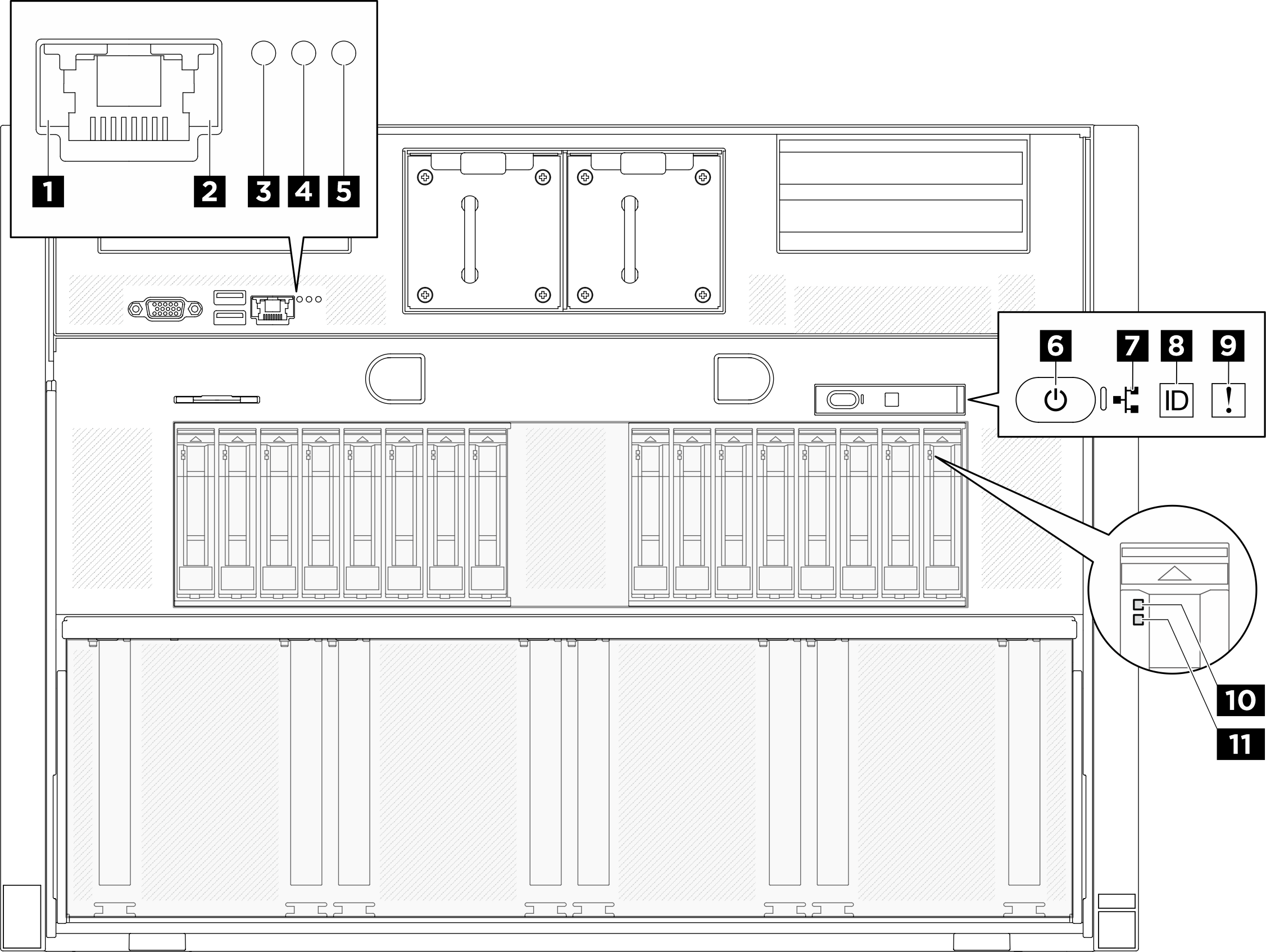
1 XCC system management port (10/100/1000 Mbps RJ-45) link LED
- Off: The network link is disconnected.
- Green: The network link is established.
2 XCC system management port (10/100/1000 Mbps RJ-45) activity LED
- Off: The server is disconnected from a LAN.
- Green: The network is connected and active.
3 Location LED (blue)
This LED is used as a presence detection LED. You can use Lenovo XClarity Controller to light this LED remotely. Use this LED to locate the server among other servers visually.
4 System error LED (yellow)
- Check the identification LED and check log LED and follow the instructions.
- Check the Lenovo XClarity Controller event log and the system error log for information about the error.
- Save the log if necessary, and clear the log afterwards.
5 RoT error LED (amber)
The RoT error LED indicates that there is a Root of Trust failure on either the XCC or UEFI image.
7 Network activity LED (green)
The network activity LED helps you identify the network connectivity and activity.
| Status | Color | Description |
|---|---|---|
| On | Green | The server is connected to a network. |
| Blinking | Green | The network is connected and active. |
| Off | None | The server is disconnected from the network. |
8 System ID button with system ID LED (blue)
Use this system ID button and the blue system ID LED to visually locate the server. Each time you press the system ID button, the state of the system ID LED changes. The LED can be changed to on, blinking, or off. You can also use the Lenovo XClarity Controller or a remote management program to change the state of the system ID LED to assist in visually locating the server among other servers.
9 System Error LED (yellow)
The system error LED helps you to determine if there are any system errors.
| Status | Color | Description | Action |
|---|---|---|---|
| On | Yellow | An error has been detected on the server. Causes might include one or more of the following errors:
| Check the LCD display or the event log to determine the exact cause of the error. |
| Off | None | The server is off or the server is on and is working correctly. | None. |
For more information about the integrated diagnostics panel, see Integrated diagnostics panel.
10 Drive activity LED (green)
Each hot-swap drive comes with an activity LED. When this LED is flashing, it indicates that the drive is in use.
11 Drive status LED (yellow)
- The LED is lit: the drive has failed.
- The LED is flashing slowly (once per second): the drive is being rebuilt.
- The LED is flashing rapidly (three times per second): the drive is being identified.