Front view
This section contains information on the front view.
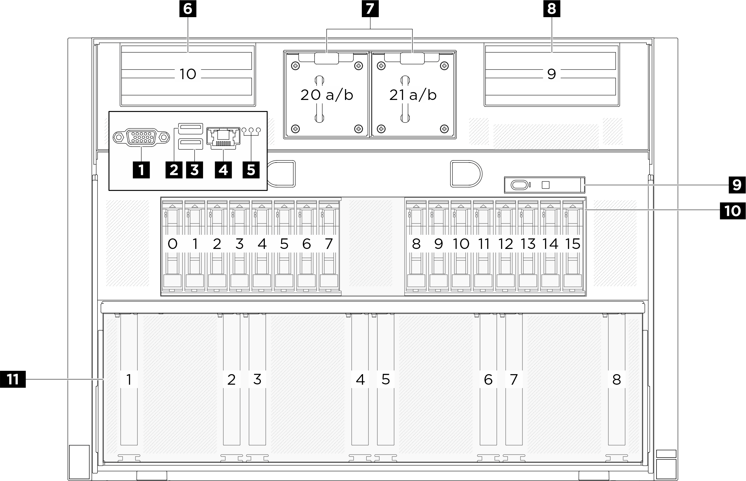
| 1 VGA connector | 2 USB 3.1 Gen 1 (5 Gbps) connector |
| 3 USB 3.1 Gen 1 (5 Gbps) connector | 4 XCC system management port (10/100/1000 Mbps RJ-45) |
| 5 Location LED/System error LED/RoT error LED | 6 PCIe riser 2 (PCIe slot 10) |
| 7 Front fans | 8 PCIe riser 1 (PCIe slot 9) |
| 9 Integrated diagnostics panel | 10 2.5-inch drive bays (bay 0 to 15) |
| 11 PCIe switch shuttle (PCIe slot 1-8) |
1 VGA connector
Connect a monitor to this connector.
2 / 3 USB 3.1 Gen 1 (5 Gbps) connector
The USB 3.1 Gen 1 (5 Gbps) connector can be used to attach a USB-compatible device, such as a USB keyboard, USB mouse, or USB storage device.
4 XCC system management port (10/100/1000 Mbps RJ-45)
The server has a 10/100/1000 Mbps RJ-45 connector dedicated to Lenovo XClarity Controller (XCC) functions. Through the system management port, you can access the Lenovo XClarity Controller directly by connecting your laptop to the management port using an Ethernet cable. Make sure that you modify the IP settings on the laptop so that it is on the same network as the server default settings. A dedicated management network provides additional security by physically separating the management network traffic from the production network.
5 Identification LED/System error LED/RoT error LED
| LED | Description and actions |
|---|---|
| 1 Location LED (blue) | This LED is used as a presence detection LED. You can use Lenovo XClarity Controller to light this LED remotely. Use this LED to locate the server among other servers visually. |
| 2 System error LED (yellow) | LED on: an error has occurred. Complete the following steps:
|
| 3 RoT error LED (Amber) | The RoT error LED helps you identify the RoT status. |
For more information on the system LEDs, see Front LEDs.
6 / 8 PCIe riser 2/1
Install PCIe adapters into these risers. See the following table for PCIe slots corresponding to the risers.
| PCIe riser | PCIe slot |
|---|---|
| 6 PCIe riser 2 | Slot 10: PCIe Gen5 x16, FH/HL (with CPU direct support) |
| 8 PCIe riser 1 | Slot 9: PCIe Gen5 x16, FH/HL (with CPU direct support) |
7 Front fans
Install front fans in this space. See Install a hot-swap fan for more information.
9 Integrated diagnostics panel
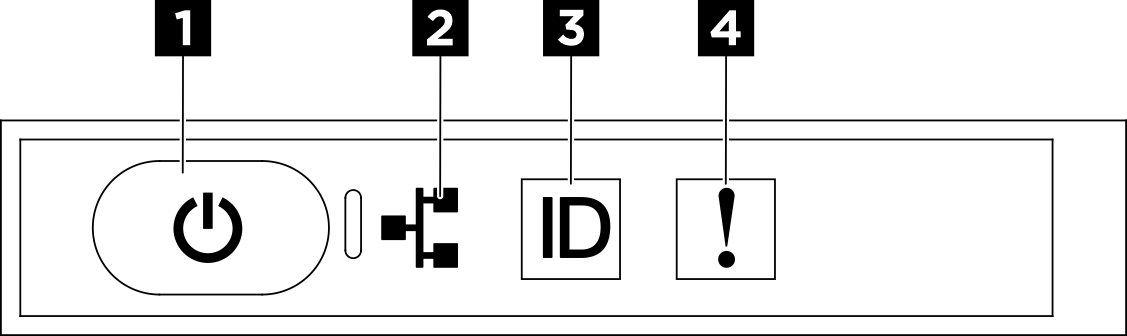
| 1 Power button with power status LED (green) | 2 Network activity LED (green) |
| 3 System ID button with system ID LED (blue) | 4 System Error LED (yellow) |
1 Power button with power status LED (green)
You can press the power button to power on the server when you finish setting up the server. You also can hold the power button for several seconds to power off the server if you cannot shut down the server from the operating system. The states of the power LED are as follows:
| Status | Color | Description |
|---|---|---|
| Off | None | No power supply is properly installed, or the LED itself has failed. |
| Flashing rapidly (four times per second) | Green | The server is turned off and is not ready to be turned on. The power button is disabled. This will last approximately 5 to 10 seconds. |
| Flashing slowly (once per second) | Green | The server is turned off and is ready to be turned on. You can press the power button to turn on the server. |
| Lit | Green | The server is turned on. |
2 Network activity LED (green)
The network activity LED helps you identify the network connectivity and activity.
| Status | Color | Description |
|---|---|---|
| On | Green | The server is connected to a network. |
| Blinking | Green | The network is connected and active. |
| Off | None | The server is disconnected from the network. |
3 System ID button with system ID LED (blue)
Use this system ID button and the blue system ID LED to visually locate the server. Each time you press the system ID button, the state of the system ID LED changes. The LED can be changed to on, blinking, or off. You can also use the Lenovo XClarity Controller or a remote management program to change the state of the system ID LED to assist in visually locating the server among other servers.
4 System Error LED (yellow)
The system error LED helps you to determine if there are any system errors.
| Status | Color | Description | Action |
|---|---|---|---|
| On | Yellow | An error has been detected on the server. Causes might include one or more of the following errors:
| Check the LCD display or the event log to determine the exact cause of the error. |
| Off | None | The server is off or the server is on and is working correctly. | None. |
For more information about the integrated diagnostics panel, see Integrated diagnostics panel.
10 2.5-inch drive bays (bay 0 to 15)
Install 2.5-inch NVMe drives to these bays. See Install a 2.5-inch hot-swap drive for more information.
For more information on the drive LEDs, see Front LEDs.
11 PCIe switch shuttle (PCIe slot 1-8)
- PCIe Gen5 x16, FH/HL