Remove the Lenovo Processor Neptune Core Module
Follow the instructions in this section to remove the Processor Neptune® Core Module (NeptCore).
This task must be operated by trained technicians that are certified by Lenovo Service. Do not attempt to remove or install the part without proper training and qualification.
Contact Lenovo Professional Services team for help when installing the part for the first time.
Make sure to have the water loop shipping bracket available to properly perform this task.
About this task

Read Installation Guidelines and Safety inspection checklist to ensure that you work safely.
Power off the server and peripheral devices and disconnect the power cords and all external cables. See Power off the server.
Prevent exposure to static electricity, which might lead to system halt and loss of data, by keeping static-sensitive components in their static-protective packages until installation, and handling these devices with an electrostatic-discharge wrist strap or other grounding system.
- Each processor socket must always contain a cover or a cold plate. When removing or installing a cold plate assembly, protect empty processor sockets with a cover.
- Do not touch the processor socket or processor contacts. Processor-socket contacts are very fragile and easily damaged. Contaminants on the processor contacts, such as oil from your skin, can cause connection failures.
- Do not allow the thermal grease on the processor or cold plate to come in contact with anything. Contact with any surface can compromise the thermal grease, rendering it ineffective. Thermal grease can damage components, such as the electrical connectors in the processor socket.
| Torque screwdriver type list | Screw Type |
|---|---|
| Torx T30 head screwdriver | Torx T30 screw |
Procedure
- Disconnect the leakage detection sensor module cable from the connector on the system board assembly.Figure 1. Disconnecting leakage detection sensor module
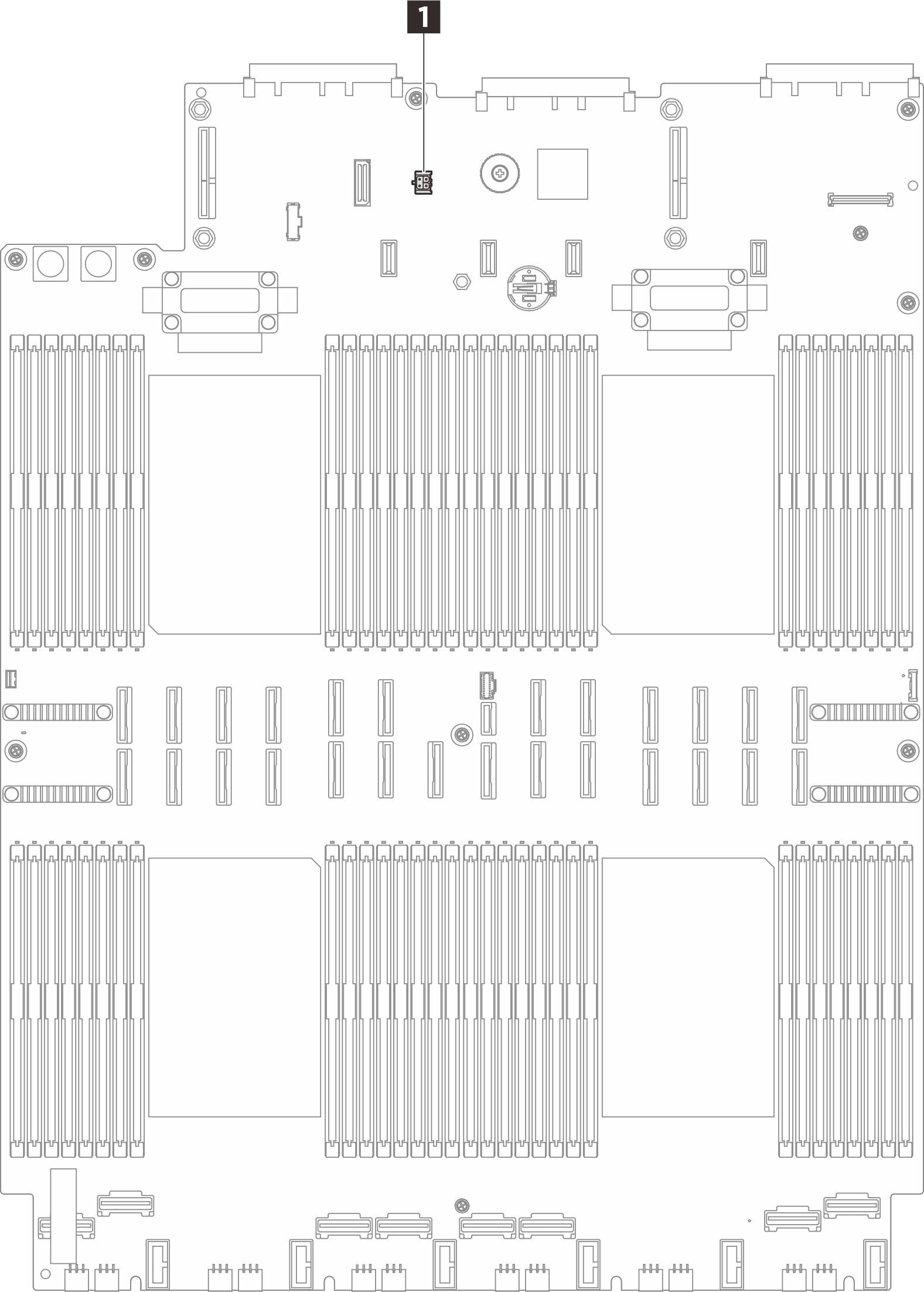
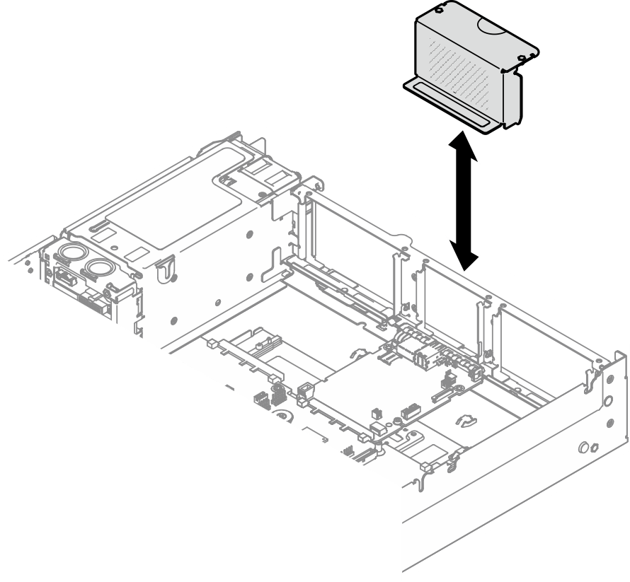
1 Leakage sensor connector - Remove the riser filler.Figure 2. Removing riser filler
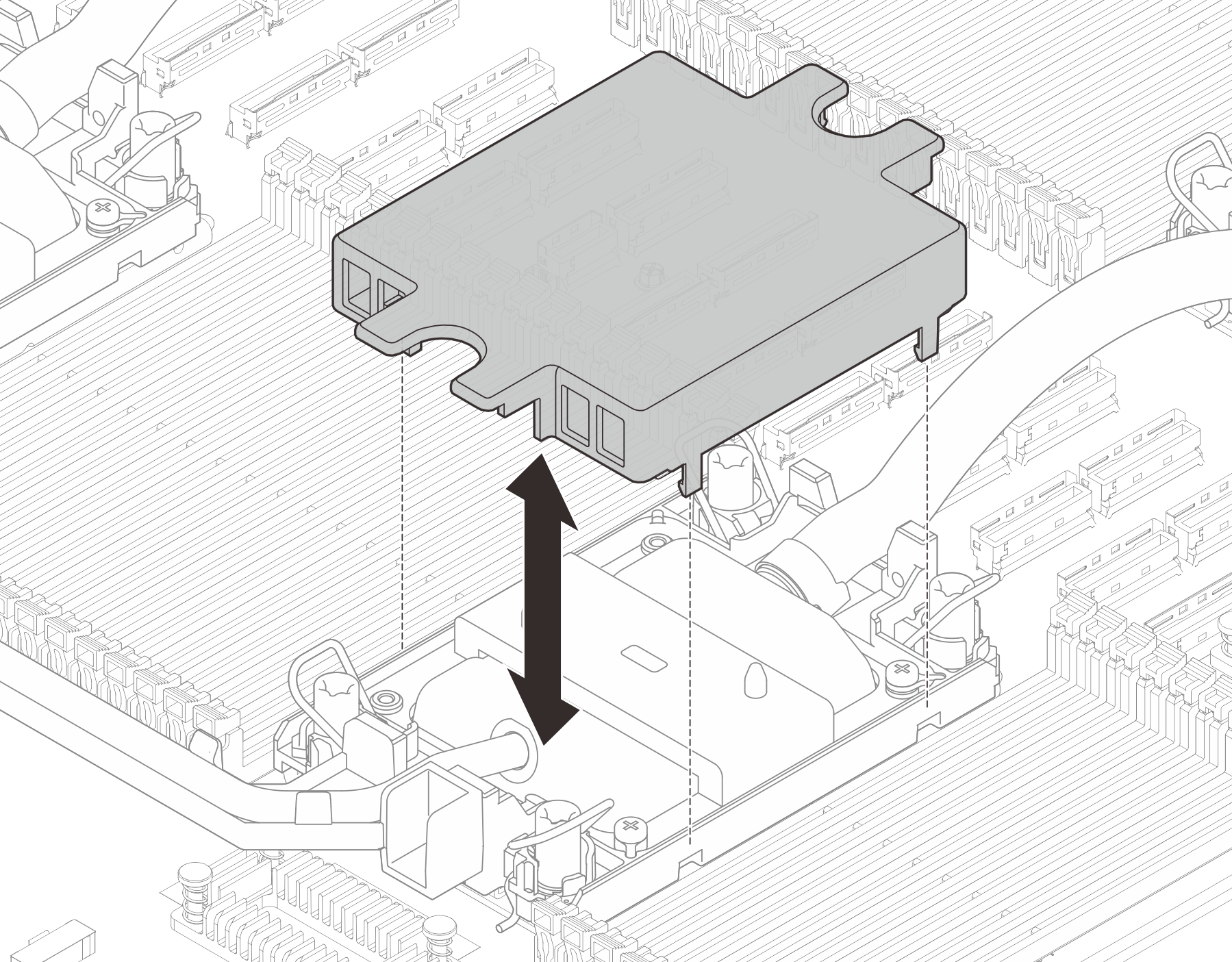
- Remove the cold plate covers.Figure 3. Removing cold plate covers
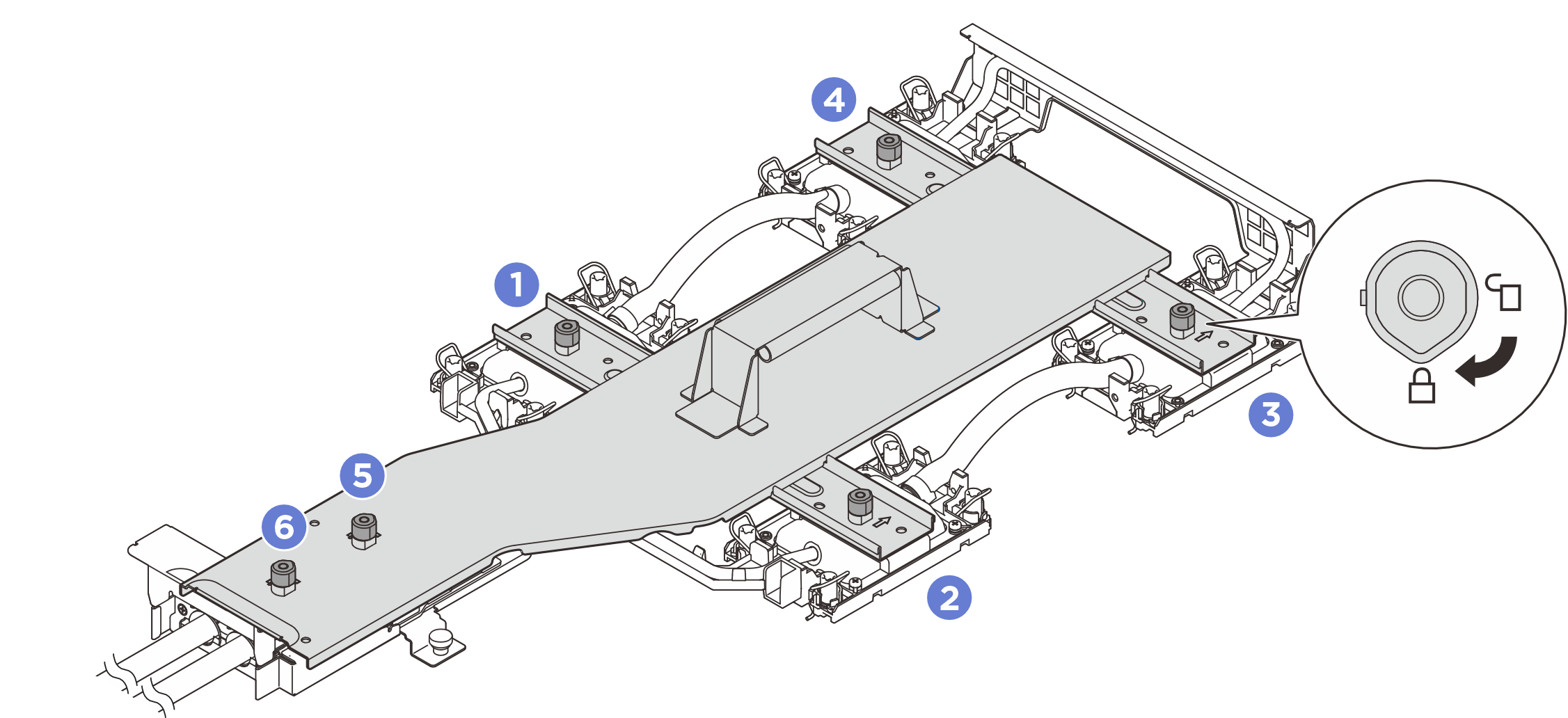
- Align and place the cold plate carrier onto the cold plate assembly.Figure 4. Installing cold plate carrier
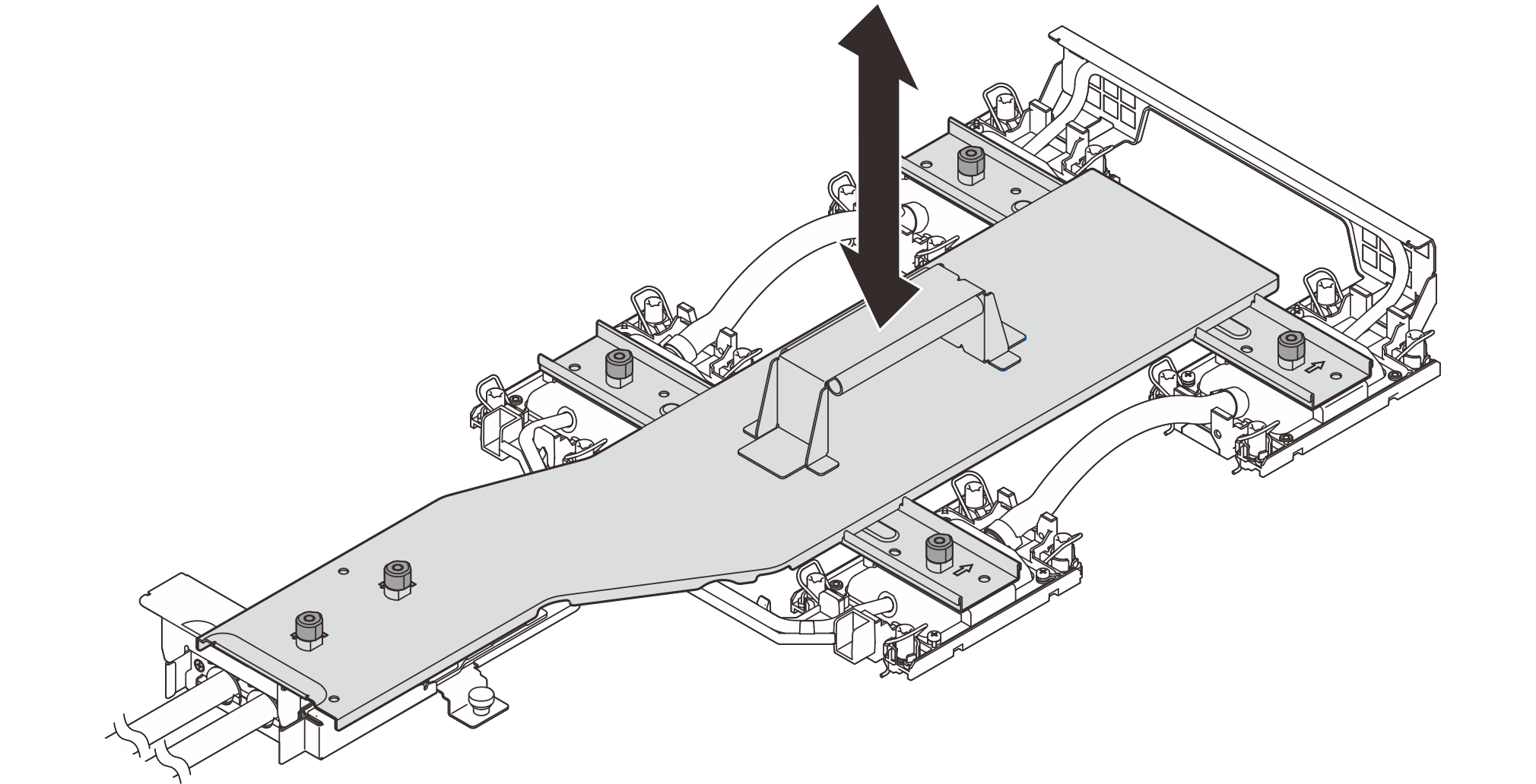
- Rotate all plungers clockwise to the locked position in the installation sequence shown on the carrier label.Figure 5. Securing cold plate carrier
- Loosen all the Torx T30 nuts on the cold plate assembly.Figure 6. Loosening Torx T30 nuts
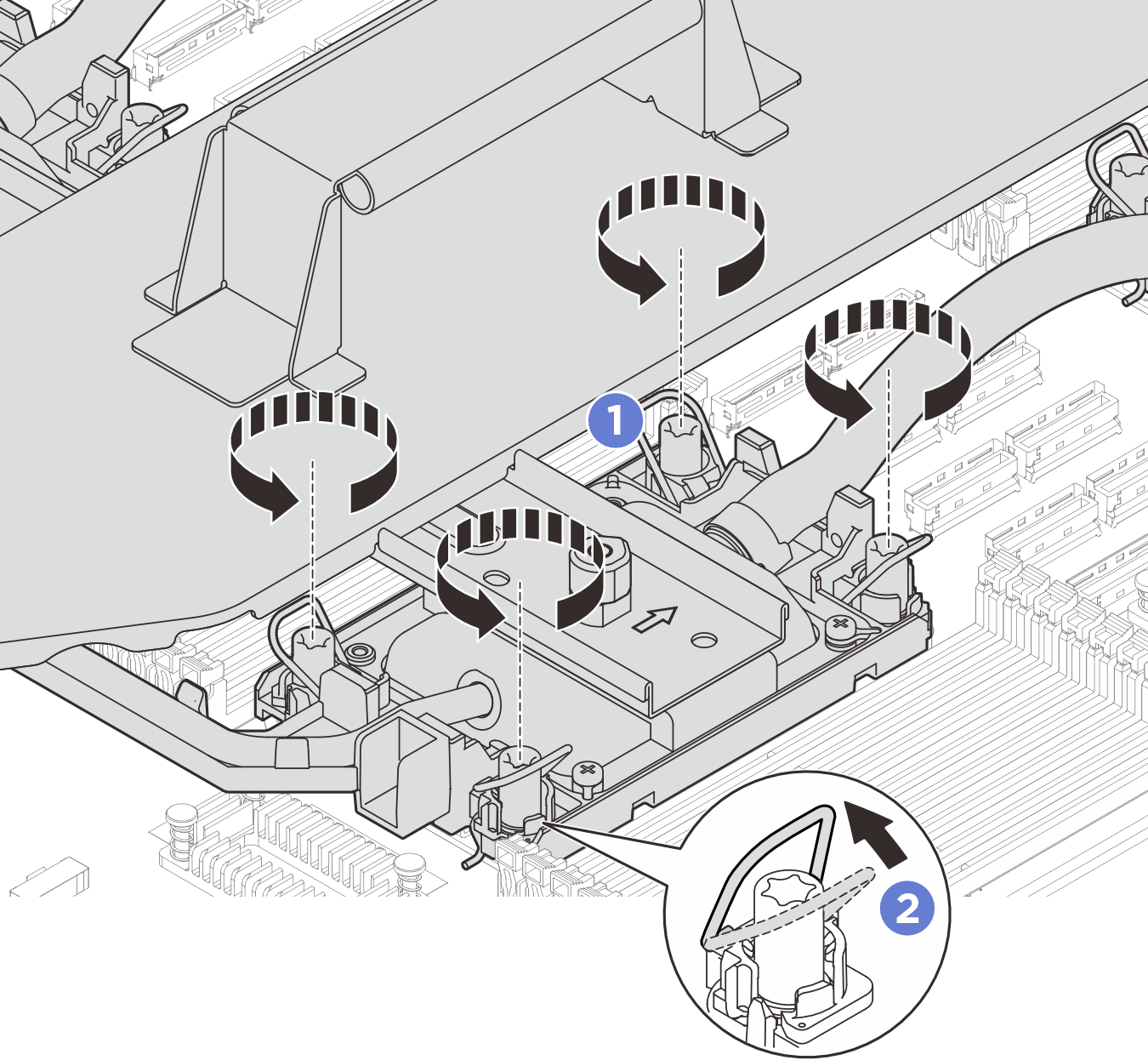
 Fully loosen the Torx T30 nuts on the cold plate assembly.
 Rotate the anti-tilt wire bails inward.
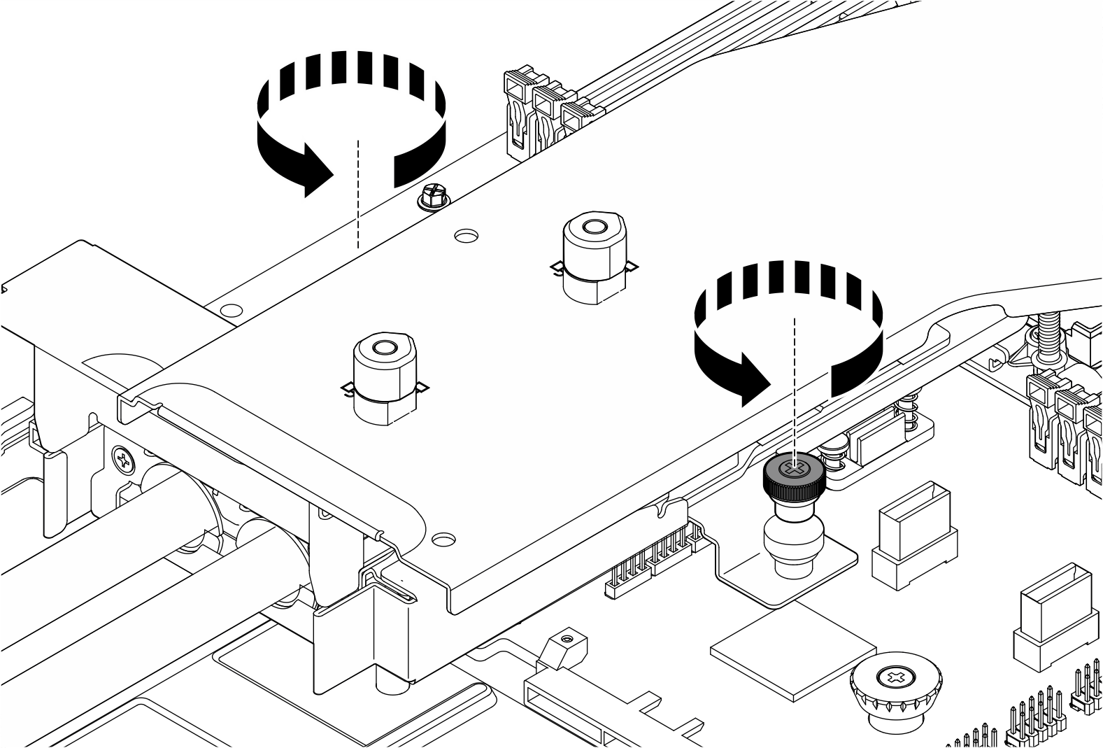
- Loosen the thumbscrews. Use a screwdriver if necessary.Figure 7. Removing cold plate assembly
- Remove the cold plate assembly.Figure 8. Removing cold plate assembly
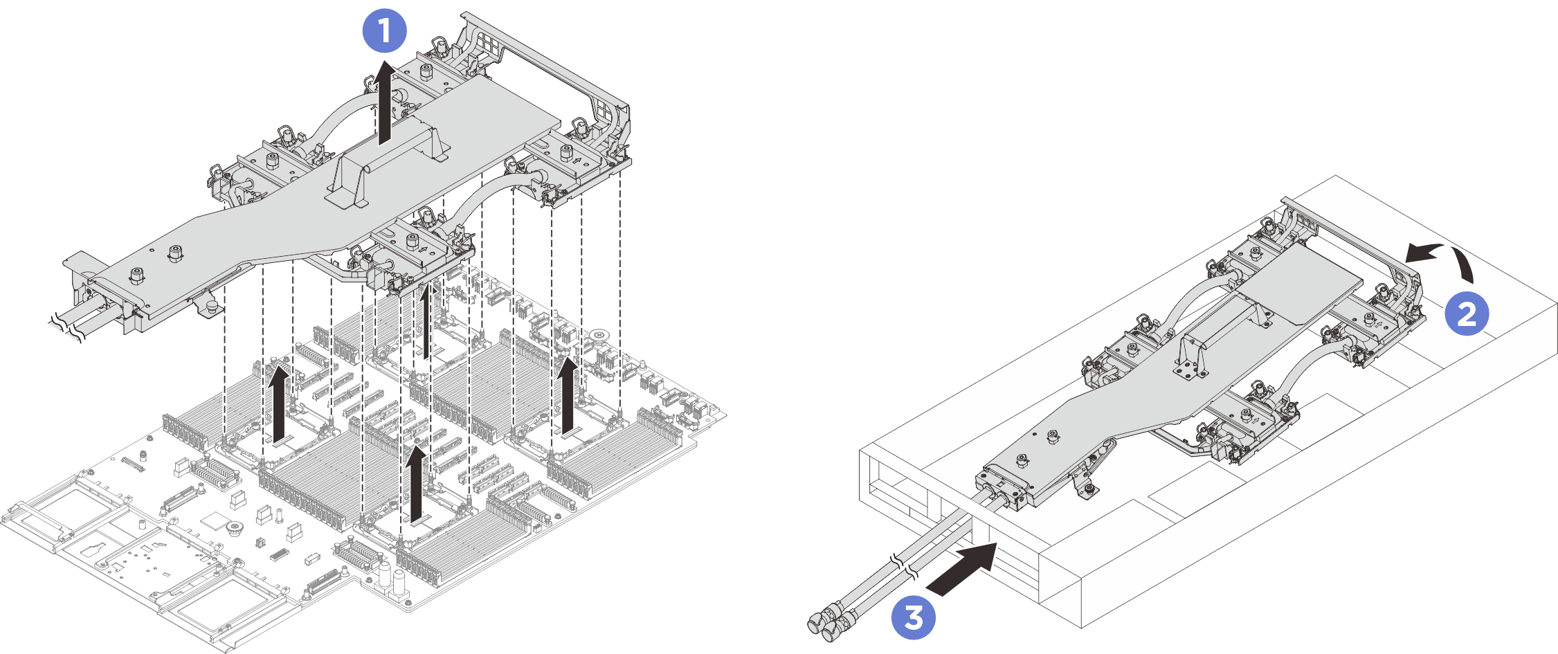
- Hold the handle on the cold plate assembly and lift it from the system board assembly.
- Pivot the front of the cold plate assembly at an angle.
 Gently slide the cold plate assembly towards the front of the chassis; then, carefully lift the hoses of cold plate assembly out of the chassis.
If you are instructed to return the component or optional device, follow all packaging instructions, and use any packaging materials for shipping that are supplied to you.
Demo video