Top view
This section contains information on the top view of the server.
The left figure below shows the top view with the top cover and upper processor board (CPU BD) air baffle removed; and the right figure below shows the top view with the top cover, upper processor board (CPU BD), system I/O board and interposer assembly, and lower processor board (MB) air baffle removed.
Note
- Depending on the configuration, your server might be slightly different from the image.
- The primary chassis is shown below as an example, the secondary chassis is similar.
Figure 1. Server top view
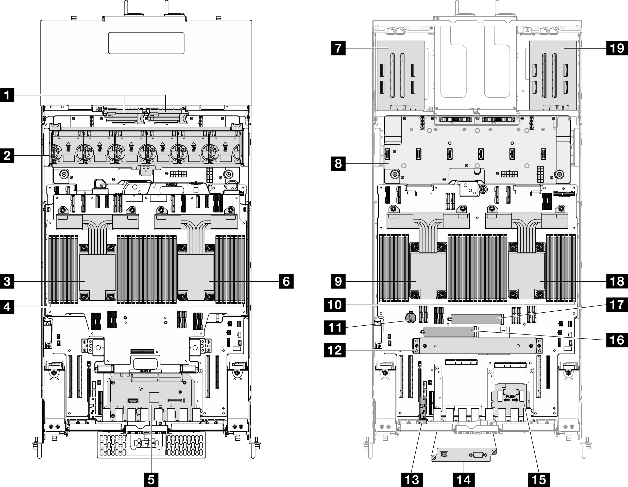
| 1 Power interposer boards (PIB) | 11 CMOS battery |
| 2 Fan and fan cage assembly | 12 Support bracket |
| 3 CPU7/CPU6 | 13 Sideband card |
| 4 Memory modules A1-T2 (Upper processor board (CPU BD)) | 14 Serial port assembly (Primary chassis only) |
| 5 System I/O board and interposer assembly (Primary chassis only) | 15 Front operator panel and front operator panel cage (Primary chassis only) |
| 6 CPU5/CPU4 | 16 M.2 slot 1 |
| 7 Left riser card | 17 M.2 slot 2 |
| 8 Power distribution board (PDB) | 18 CPU0/CPU1 |
| 9 CPU2/CPU3 | 19 Right riser card |
| 10 Memory modules A1-T2 (Lower processor board (MB)) |
Give documentation feedback