System I/O board and interposer assembly switches
The following illustrations show the location of the switches on the system I/O board and interposer assembly.
Important
Before you change any switch settings or move any jumpers, turn off the server; then, disconnect all power cords and external cables. Review the following information:
- Any system I/O board and interposer assembly switch or jumper block that is not shown in the illustrations in this document are reserved.
Note
If there is a clear protective sticker on the top of the switch blocks, you must remove and discard it to access the switches.
Figure 1. System I/O board and interposer assembly switches
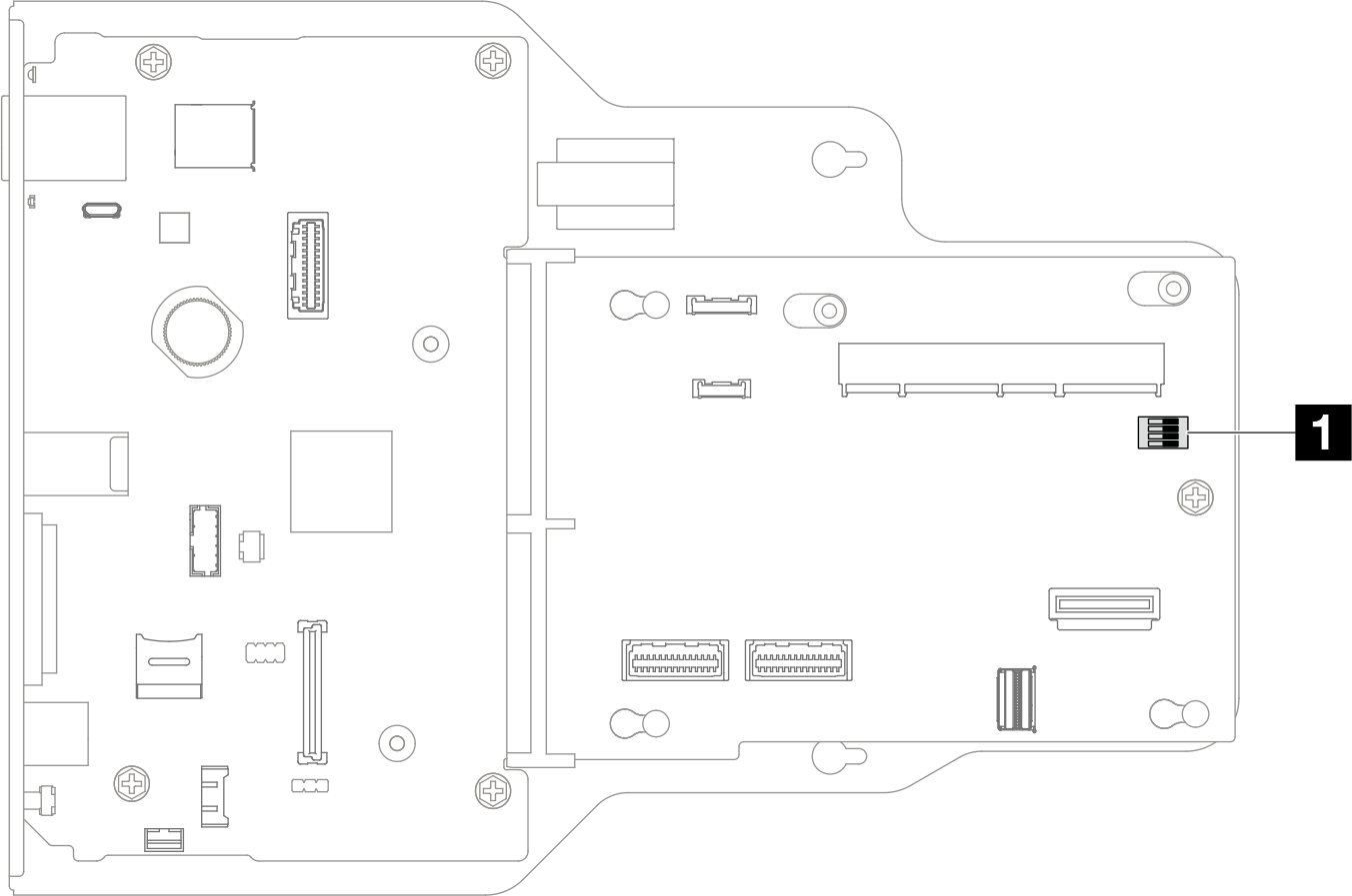
| 1 SW1 |
SW1 switch block
The following table describes the functions of the SW1 switch block on the system I/O board and interposer assembly.
Switch number | Jumper Name | Default position | Function |
|---|---|---|---|
SW-1 | Low security | Off | Keeping this switch in the On position allows transitioning between signed official IMM builds and IMM test signed builds, and bypasses CRTM boot check of iMM firmware. |
SW-2 | Reserved | Off | Reserved |
SW-3 | Reserved | Off | Reserved |
SW-4 | Reserved | Off | Reserved |
Give documentation feedback