Front view
This section contains information about the controls, LEDs, and connectors on the front of the server.
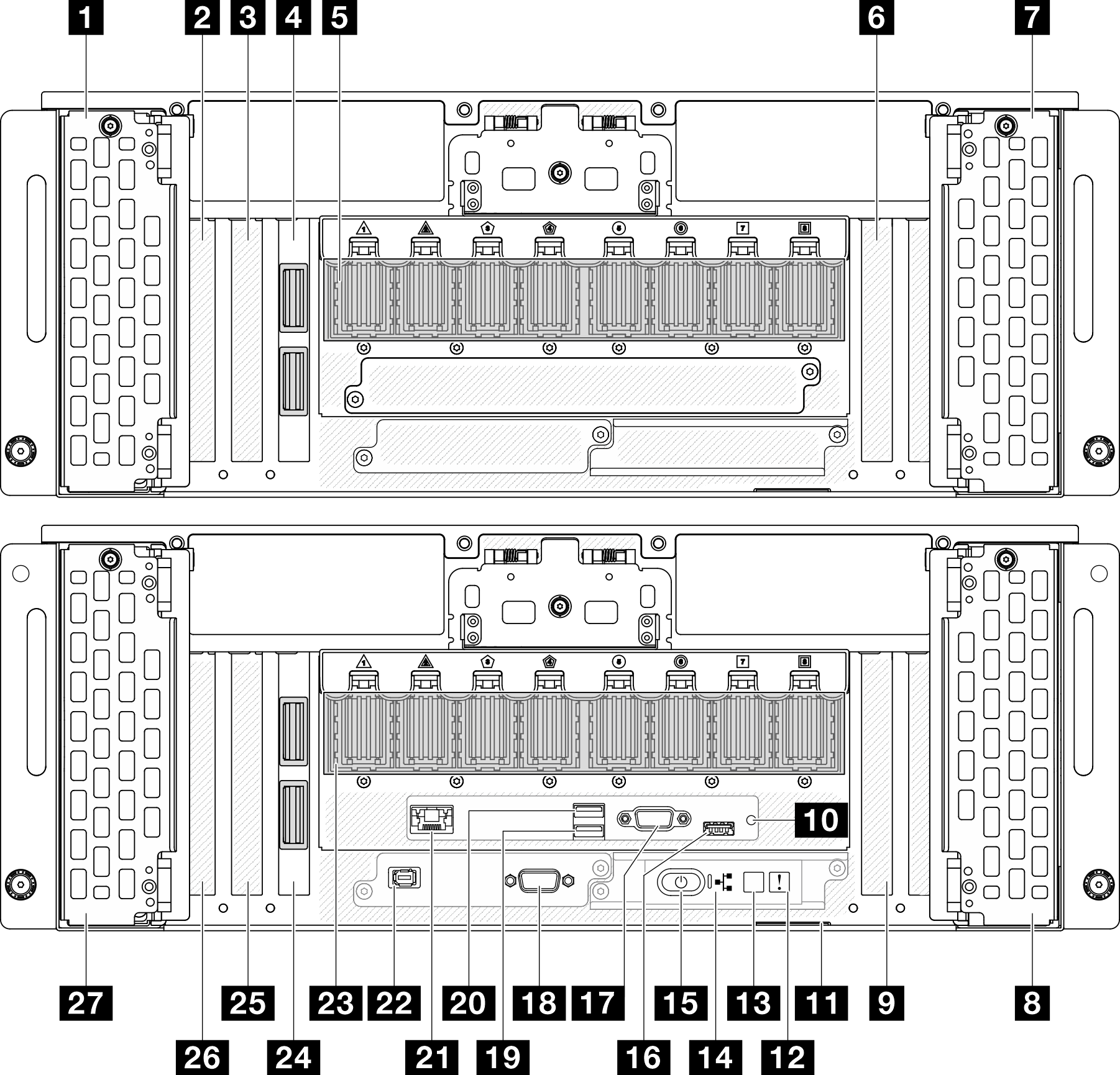
1 Drive bays 8-11 | 15 Power button/LED (green) |
2 PCIe slot S1 | 16 USB 2.0 connector with Lenovo XClarity Controller management |
3 PCIe slot S2 | 17 VGA connector |
4 Sideband card (Secondary chassis) | 18 Serial port |
5 UPI module (Secondary chassis) | 19 USB 3.2 Gen 1 (5 Gbps) |
6 PCIe slot S3 | 20 USB 3.2 Gen 1 (5 Gbps) |
7 Drive bays 12-15 | 21 XCC system management port (1 GB RJ-45) |
8 Drive bays 4-7 | 22 External diagnostics connector |
9 PCIe slot P3 | 23 UPI module (Primary chassis) |
10 NMI button | 24 Sideband card (Primary chassis) |
11 Pull-out information tab | 25 PCIe slot P2 |
12 System error LED (yellow) | 26 PCIe slot P1 |
13 System ID button/LED (blue) | 27 Drive bays 0-3 |
14 Network activity LED (green) |
1 / 7 / 8 / 27 Drive bays
Install drives to these bays. See Install a hot-swap drive.
Figure 2. 2.5-inch drive bay numbering 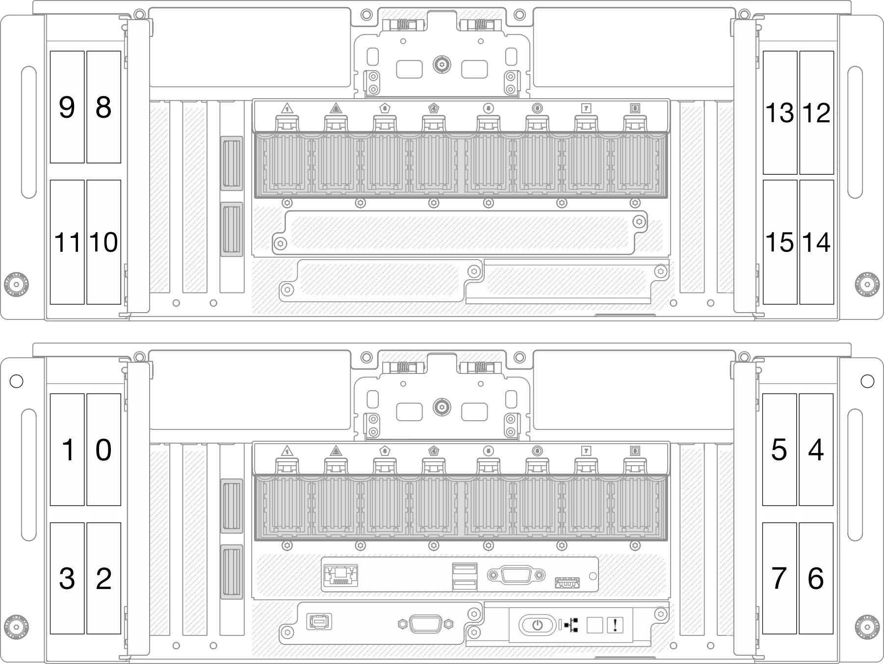 | Figure 3. E3.S drive bay numbering 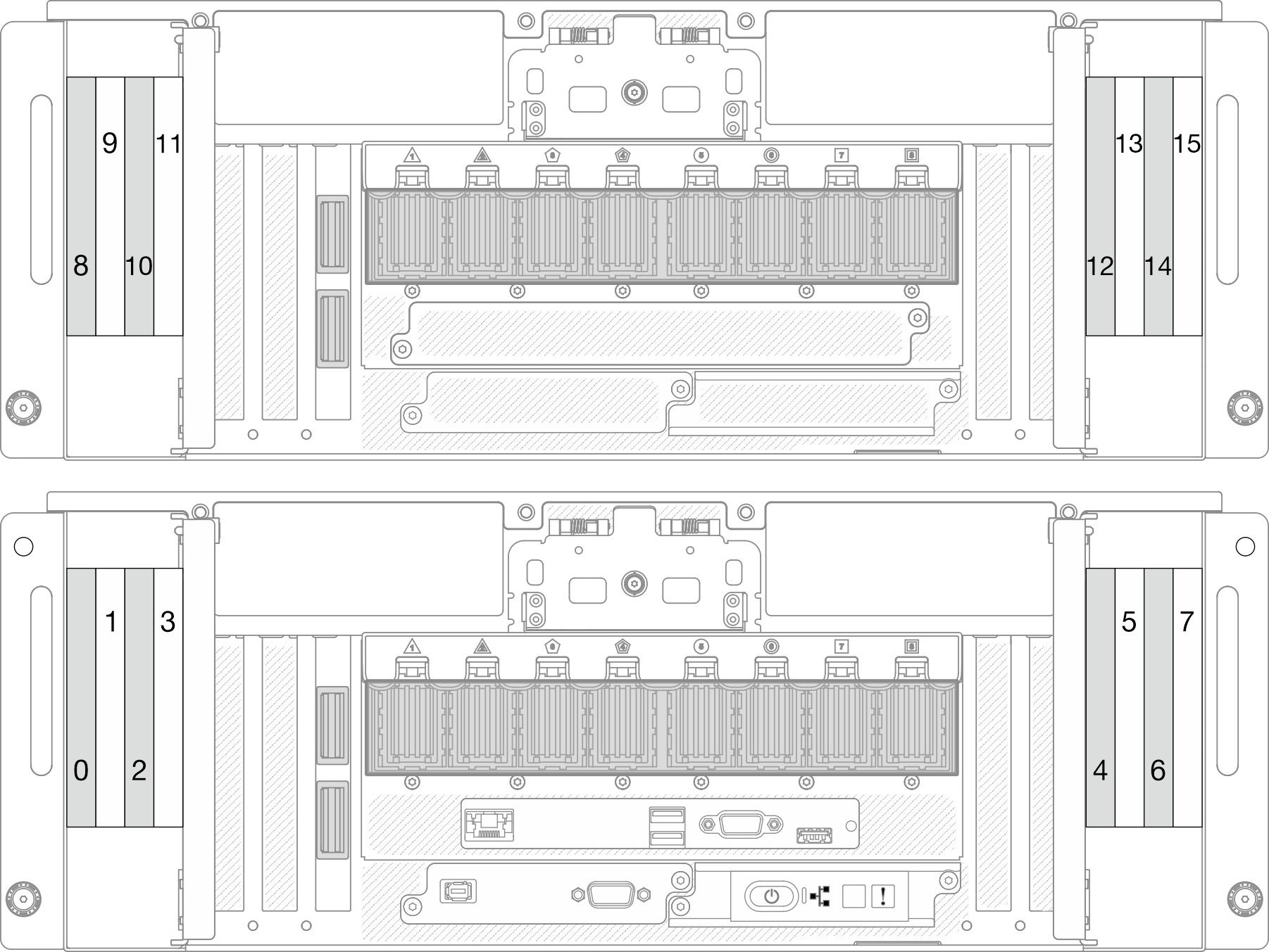 |
2 / 3 / 6 PCIe slots S1-S3
Install PCIe adapters into these PCIe slots. See Install a PCIe adapter.
4 / 24 Sideband card
Connect the external sideband cables to these sideband cards.
5 / 23 UPI module
Connect the external UPI cables to these UPI modules.
9 / 25 / 26 PCIe slots P1-P3
Install PCIe adapters into these PCIe slots.
11 Pull-out information tab
This tab contains network information such as MAC address and XCC network access label.
12 System error LED (yellow)
| Status | Color | Description | Action |
|---|---|---|---|
| On | Yellow | An error has been detected on the server. Causes might include one or more of the following errors:
| Check system logs to identify the failed part. |
| Off | None | The server is off or the server is on and is working correctly. | None. |
13 System ID button/LED (blue)
Use this system ID button and the blue system ID LED to visually locate the server. Each time you press the system ID button, the state of the system ID LED changes. The LED can be changed to on, blinking, or off. You can also use the Lenovo XClarity Controller or a remote management program to change the state of the system ID LED to assist in visually locating the server among other servers.
14 Network Activity LED (green)
| Status | Color | Description |
|---|---|---|
| On | Green | The server is connected to a network. |
| Blinking | Green | The network is connected and active. |
| Off | None | The server is disconnected from the network. |
15 Power button/LED (green)
| Status | Color | Description |
|---|---|---|
| Off | None | Power is not present, or the power supply has failed. |
| Fast blinking (about four flashes per second) | Green |
|
| Slow blinking (about one flash per second) | Green | The server is off and is ready to be powered on (standby state). |
| Solid on | Green | The server is on and running. |
16 USB 2.0 connector with Lenovo XClarity Controller management
Connect a USB 2.0 device, such as a mouse, keyboard, or other devices, to this connector.
Connection to Lenovo XClarity Controller is primarily intended for users with a mobile device running the Lenovo XClarity Controller mobile application. When a mobile device is connected to this USB port, an Ethernet over USB connection is established between the mobile application running on the device and the Lenovo XClarity Controller.
Select Network in BMC Configuration to view or modify settings.
Four types of settings are available:
Host only mode
In this mode, the USB port is always solely connected to the server.
BMC only mode
In this mode, the USB port is always solely connected to Lenovo XClarity Controller.
Shared mode: owned by BMC
In this mode, connection to the USB port is shared by the server and Lenovo XClarity Controller, while the port is switched to Lenovo XClarity Controller.
Shared mode: owned by host
In this mode, connection to the USB port is shared by the server and Lenovo XClarity Controller, while the port is switched to the server.
17 VGA connector
Connect a monitor to this connector.
18 Serial port connector
Connect a 9-pin serial device to this connector. The serial port is shared with XCC. XCC can take control of the shared serial port to redirect serial traffic, using Serial over LAN (SOL).
19 / 20 USB 3.2 Gen 1 (5 Gbps) connector
The USB 3.2 Gen 1 (5 Gbps) connector can be used to attach a USB-compatible device, such as a USB keyboard, USB mouse, or USB storage device.
21 XCC system management port (10/100/1000 Mbps RJ-45) (1 GB RJ-45)
The server has a 1 GB RJ-45 connector dedicated to Lenovo XClarity Controller (XCC) functions. Through the system management port, you can access the Lenovo XClarity Controller directly by connecting your laptop to the management port using an Ethernet cable. Make sure that you modify the IP settings on the laptop so that it is on the same network as the server default settings. A dedicated management network provides additional security by physically separating the management network traffic from the production network.
22 External diagnostics connector
Connect the external diagnostics handset to this connector. See External Diagnostics Handset for more details.